Homebrew Pinball #3, Part 15

Cross posted from the original Pinside thread, this is one of many posts regarding my third homebrew pinball machine, creatively nicknamed 'P3'


Mounted the final mech today, the outlane saver. I'm having some trouble with its reliability currently. It keeps going up too high and getting stuck above the playfield. I added a bolt across the bottom to stop it from going too far, but then the bolt got stuck instead. So I added a spring to prevent the bolt from hitting the bottom of the coil so hard, but the spring reduced the travel enough to make the mechanism weak. I'll need to play some with adjusting the lengths of the parts in an attempt to lengthen the travel, or maybe make a custom bracket to allow everything to be longer (currently I'm just using a regular up-post/vuk bracket).

Here's a video of what the saver does when it doesn't get stuck or bottom out:

It's super strong and just sends the ball flying back onto the playfield if you time it right. I like having an outlane saver that doesn't save you completely, it just keeps the ball in play. The magna save does the same thing to a lesser extent, and the mini playfield shot between the flippers also manages pretty well, since your shot tends to go right into the right slingshot and out of control. This can be good or bad, depending on your playfield situation, since chances are once it gets bouncing around it's going to knock down a few drop targets, which will help you complete your hand, but they might not be the cards you want to make a good hand.

If you fire the popper too late though, you'll end up with a ball that, due to its left/down motion, leaves the metal guide sideways, and just flies off to the left. I've had it end up in the left inlane, the left outlane, all the way down in the mini playfield, and even somehow jumping backwards into the trough. I'll have to put up some air ball protection to make sure it always returns to the playfield somehow.

Posted Thursday, September 17, 2020
at 04:07 PM


Tags: Blog Post, Pinball, Project, P3,

Homebrew Pinball #3, Part 14

Cross posted from the original Pinside thread, this is one of many posts regarding my third homebrew pinball machine, creatively nicknamed 'P3'


Next step was adding the diverter to the shooter lane. I have a bally gate mech, but it's designed for low speed inlanes, not very flowy. So I 3d printed a much smoother gate:

This mostly works, but I had issues where very fast balls would somehow get too much horizontal force out of it and hit the top post of the slingshot instead of directing down into the inlane. So I had to take 3 iterations of straightening it and adjusting the curve to get it to a point where even the fastest ball I can manage still goes towards the inlane, while a slow ball that just drops from the end still has a good chance of getting to the inlane.
Original:
Final:
It's a fine line because it needs to be able to fit behind the right drop targets and not block the shooter lane, so it can't be too wide or too straight.

I also added a little guide on the slingshot to smooth the transition, since the ball tended to bounce back and forth before coming down to the flipper

With the diverter and the left inlane done, I now have two more shots I can test.

First, the spinner/orbit:

This works, although it's a bit clunkier than I'd like. The spinner eats up some of the energy from the ball. I'll have to do some more tests with the spinner removed to see if there's any geometry improvements I can do. My upper arch isn't optimally designed, since it has a large flat part, which gives the ball time to 'drop' at the top and not follow the other side curve smoothly. Plus, with the lanes on both sides of the playfield, the shots hit the side walls at a more oblique angle which is probably leading to a less smooth shot. Might need to get the camera in slo-mo to see for sure

Second, the under-ramp/orbit:
I was worried about this shot since the left side curve of the upper arch is tighter than the right due to the ramp and upper eject area being in the way, so the ball had a the potential to hit the wall and bounce off at a ~25 degree angle, missing the curve completely, but luckily this doesn't seem to be the case somehow. In fact, it's smooth. SUPER smooth. And ridiculously fast. I took 20 shots at it, and didn't manage to loop it even once due to the sheer speed of the ball coming down the inlane. But I'm also not very good at that type of repeating shot. Can't wait to get this flipping enough to see some better players take a crack at it.

Posted Thursday, September 17, 2020
at 03:23 PM


Tags: Blog Post, Pinball, Project, P3,

Homebrew Pinball #3, Part 13

Cross posted from the original Pinside thread, this is one of many posts regarding my third homebrew pinball machine, creatively nicknamed 'P3'


Printed some inlane guides, and made a one way gate for the left inverted inlane.

Had a lot of trouble getting the inverted inlane to work properly. I made it with slots so it could be adjusted up and down, but if I put it lower, than a ball that just dribbled into the lane above the separator wireform wouldn't manage to make it over the gap, and if I put it higher to save those balls, then a fast ball coming down from the top of the playfield would hit the back of the slingshot and drain. There was also a weird issue that I could never reproduce by hand where a ball dropped from a middling height would somehow rattle to a stop and then fall down the outlane.

I designed this little gate to make it work at any speed. It works surprisingly well, although I'm sure it's going to break sooner or later since it's quite flimsy. I'll have to come up with a more solid way to accomplish it..

Posted Wednesday, September 16, 2020
at 03:55 PM


Tags: Blog Post, Pinball, Project, P3,

Homebrew Pinball #3, Part 12

Cross posted from the original Pinside thread, this is one of many posts regarding my third homebrew pinball machine, creatively nicknamed 'P3'


Some more small build updates...

Made these little clips for the ball arch. They go on top of the side rails and clamp one long piece of stainless down to the playfield. Eventually I'll probably drill some holes through it to mount it, similar to how williams games do it, but for now this will allow some easy adjustment while I play with the curves

In the spirit of getting as much mounted as possible to figure out placement under the playfield, I started mounting all the rollover stars. Had to special order a 1-3/16 forstner bit (dang, these are expensive!) to cut these. Manually drilled down the proper distance to get them flush, was a big pain.

My biggest innovation yet, a target in front of the spinner wire instead of a mini post. Should be back handable from the right flipper

Threw together a 60 degree kicker for the upper eject hole as it was the only shape mech that would fit with the drop targets so close. Didn't want to pay for a full mech so I used a random plunger from a vuk or kickback, not sure. The plunger was too long, so I just put some 1/2" standoffs under the mech

Needed a down-post for the mini playfield diverter, so I 3D printed one. It just presses up against the bottom of the playfield to stop it at max height, and uses a plunger from a williams drop reset mech that has a built in thread on the end. I had problems with the rubber I put on it sticking in the hole of the playfield, and being too bouncy when up, so I switched later to just a straight plastic post on top.

Posted Monday, September 14, 2020
at 06:08 PM


Tags: Blog Post, Pinball, Project, P3,

Homebrew Pinball #3, Part 11

Cross posted from the original Pinside thread, this is one of many posts regarding my third homebrew pinball machine, creatively nicknamed 'P3'


Bottom of the playfield already getting pretty crowded...

Before I got much farther, I realized I'd forgotten to cut the magnet holes in the bottom. Those will need to be done with the router, which needs some space, so I'll need to remove all the mechs in the area and the support rails.

I very scientifically traced the magnet out, and routed out a depression:

I wanted to hook it up to test, but that meant installing the relay somewhere. When I was looking around for the best place to put it, I realized that this was a bit dangerous, as I didn't know where any of the lights, switches, or wiring was going to go. I tried to mark out roughly where I was picturing things, and that actually left me with no safe spaces to put the relay! I'm sure once it's all done there'll be room, especially in the middle of the upper playfield area, but I have no idea what sort of lights are going to be up there now, so I want to avoid mounting anything there. Then, I realized the one area I knew was safe...

Posted Monday, September 14, 2020
at 09:39 AM


Tags: Blog Post, Pinball, Project, P3,

Homebrew Pinball #3, Part 10

Cross posted from the original Pinside thread, this is one of many posts regarding my third homebrew pinball machine, creatively nicknamed 'P3'


In order to get the sequenced firing working to test the 5 bank, I had to get some more control going on. Previously when testing the flippers I was just editing the driver board firmware manually to configure coils. I made a custom MPU board with hookup for up to 8 external driver boards for solenoids, lights, displays, etc. It's powered via a raspberry pi for simplicity, and also has support for an 8x16 switch matrix. Here's my first test setup, with the two boards just screwed to a spare piece of foam core.

The driver board can have each solenoid configured with a default pulse time, a maximum on time, and PWM duty cycle. The switch matrix and board I/O are handled via a small Java app for now, which can be connected to via a socket to send commands. The game code will eventually send those commands, but for now it makes for easy testing to just connect directly to the socket via PuTTY and type them in. To fire the 5 bank, I just made a quick bash script to send six commands in a loop with some pauses in between.

Posted Sunday, September 13, 2020
at 11:22 PM


Tags: Blog Post, Pinball, Project, P3,

Homebrew Pinball #3, Part 9

Cross posted from the original Pinside thread, this is one of many posts regarding my third homebrew pinball machine, creatively nicknamed 'P3'


Started wiring all my drop target banks at my workbench. Each will have a connector for easy removal. Not going to bother with that on every mech, since most are pretty simple and either serviceable from the playfield or unlikely to need service, but drop targets and pop bumpers are another story.

Realized I'd made a big mistake during initial planning... Most of my banks are williams or gottlieb, which is fine, but the 5 bank on the right is a bally, which I chose because they have thicker targets, which will make shooting past them into the shooter lane smoother, and they had 'memory', so I could knock them down with code if needed to make the shooter lane shot easier. Problem is, Bally used 50V coils, while gottlieb and williams used 25V, and I'm using a Gottlieb transformer. A quick test revealed that, of course, the giant 50V reset coil on this bank doesn't even move when you apply 25V to it. I dug through my spare mechs box, but the only other 5 bank I had wouldn't fit due to space issues with the flipper mech immediately above it.

So I needed to get creative. How do I get 50V when my transformer only puts out 25V? With a voltage doubler! Here was my simple test setup to see if this would even work:

Basically, creative insertion of two big capacitors in the middle of a half bridge rectifier allows each to be charged by half the AC circuit to 25V. But they're wired in series, so that combines to 50V (technically, I guess it's -25V and 25V compared to the rest of the voltages in the system). Those TO-220 transistor looking things are actually just really big diodes, I think 10A each? I overspecced this thing for sure, since I couldn't find exact details on what tolerances were needed. And it worked! Bank resets just fine. You can't energize anything continuously with it since the caps will empty pretty quick, but it also recharges within a second, which is good enough for resetting one drop target bank. I got a new PCB made for this, with even more fuses (again, wasn't sure where to fuse, so I just fused everything), and a bleeder resistor so the 50V (actually, it reads as 80V for whatever reason) doesn't sit around after the machine is powered off

The issue with this of course is that, since it's operating off its own rectifier with a weird half-ground system, I can't control it via the MOSFETs on my driver boards, since they don't share a common ground. For the reset, this isn't a big deal; I can just add a relay in to control it. But I also have the 5 knock down coils. I don't want to have to wire up 6 relays for this bank. Luckily, since the knock down coils are so small, I find that they can be moved via 25V. But not enough to actually knock the target down. So I added a 4700uF cap onto my 25VDC rectifier, similar to what gottlieb did on games like Black Hole to give the kickers more juice. That gives enough strength for the knock down coils to operate 90% of the time, and I can just code them to try again if they don't detect the switch closing to handle the other 10%.

Posted Sunday, September 13, 2020
at 12:46 PM


Tags: Blog Post, Pinball, Project, P3,

Homebrew Pinball #3, Part 8

Cross posted from the original Pinside thread, this is one of many posts regarding my third homebrew pinball machine, creatively nicknamed 'P3'


From thinking about the idea of the jump from a flipper behind the main playfield, the idea turned into: what if you shot the ball up between the flippers?

It's a tough shot, but it is possible!

But, if you drain the ball from that flipper, how does it get to the outhole? Originally I wondered about doing this with a newer style below-playfield trough, so I could try to gravity feed it, but from my issues with the reverse outlane ramp, I was wary of any slopes going against the playfield slope.

I really hoped this worked when I drew it up in CAD, but wasn't sure how it would go. So many variables. I tried to leave some room to maneuver the kicker arm around to get different angles if needed, but my guess for an initial angle that I drew a line for turned out to work. I had to use a gottlieb kicker arm due to the clearances needed.

With that proof of concept looking promising, I decided to make a whole mini playfield out of it

There was not much room to work at all down there. I positioned the flipper mechas low as it could go, which resulted in this angled mech, with it pressing right up against the bottom and left side of the playfield. I couldn't put it any more to the right or else the angle for the eject would be too steep. That limited the place where the drop targets could fit. I needed to use a williams mech since they're the only style that has the coil mounted in front of the mech instead of to the side, since I had mechs to both side. And since those have a bit base plate in front of them, I couldn't put it any lower since the flipper mech was in the way, and I couldn't put it any higher and still have room for the ball to roll under the main flipper. I wanted to make sure I could disable the mini playfield area during multiball, etc to prevent anything getting stuck down there, so it needed to still have the standard outlane path. I put a down-post at the entrance to redirect balls away from the mini playfield. No room for a rubber band behind the drops either, so I figured I'd have a metal wall with some of that blue rubber sheet behind it for minimal thickness. No room for any standups to the left either since the drop mech was underneath. I also wanted to put the flipper at as low an angle as possible so that it could make the shot back between the flippers, but at the same time I wanted it to go up at least to 'level' so theoretically you could cradle the ball.

I needed to make a custom one way gate for the exit since it's so wide. I reused the little gottlieb spinner mounts from the mars playfield to mount it since there were no brackets that length either. While i was doing that I got the idea to just also put one of those behind the drop targets. Minimal width, and now I get to use the back side of the main flipper as a rebound rubber. If you knock down the drops, there's also the possibility of shooting through them and getting into the outlane area and draining that way too. Hopefully I can make this mini area super valuable, to make you willing to risk going for the targets instead of going for the saving shot immediately, or maybe if you complete the whole bank you get a ball save? We'll see how the risk reward works once you get in there...

Posted Sunday, September 13, 2020
at 11:27 AM


Tags: Blog Post, Pinball, Project, P3,

Homebrew Pinball #3, Part 7

Cross posted from the original Pinside thread, this is one of many posts regarding my third homebrew pinball machine, creatively nicknamed 'P3'


In order to test the upper playfield shots, I needed some ball guides. The shot I was most worried about was the one behind the upper right drops, since the angles looked a bit weird.
I got some 1" stainless strips, and bent one to follow the path on the playfield. I also got some #4 hex button cap screws, since they're very low profile. I can mount them near the top/bottom of the guides, and the ball won't hit them.

Made a test jig using a spare block of wood and one of my big C clamps for a quick test:

Success! Now to mount it for real...
I've never found a good place to buy these premade, so I'm making my own L brackets to mount the guides. I got a strip of 1/2"x1/16" aluminum, and cut it into ~1.5" sections:
Bend it into an L using my vice:
then drill both ends, one for the #4 machine screw and one for a #6 wood screw
Then, mount it using the button head screw and a nylon lock nut on the back

In the back you can also see my next 'custom' mech, a controlled gate:

As is going to be common, I don't know the dimensions of a lot of the mechs available online from marco/pbl, and I don't want to spend $50 to find out if it fits, so I'm making a lot of this myself... This one is made from a normal one way gate, with a piece of slightly flexible thin metal rod (I think piano wire from a PBR kit) that I bent so that it sticks through the housing and when I pull down on it, holds the gate open. Then I used a spare slingshot bracket, a random coil, and a custom plunger I made from some round stock, with a hole through the top to stick the piano wire on, and a threaded hole on the side to clamp down on the wire. The wire's hole is pretty deep, allowing me to adjust the 'pull' of the mech, and the set screw also acts as a holder for the return spring. Luckily since the piano wire is so flexible, the mech can be positioned pretty freely, as you can see here where the whole wire is going through the wood at an angle... I'll need to figure out exactly where this needs to go eventually, but for now it works.

Posted Saturday, September 12, 2020
at 10:49 AM


Tags: Blog Post, Pinball, Project, P3,

Homebrew Pinball #3, Part 6

Cross posted from the original Pinside thread, this is one of many posts regarding my third homebrew pinball machine, creatively nicknamed 'P3'


Now for the fun part: my first board!

I've been hoping to avoid FAST/PROC for cost reasons, and rolling my own sounded like fun, so I designed these. 2"x4", 16 drivers controlled by their own dedicated processor. 12 'high power' drivers using a step up chip to convert the CPU's 3V signals to 5V, 4 low power drivers for things like relays, which can also be configured as fast react inputs by replacing the mosfet (an IRL540N) with a jumper wire and all controllable via SPI. I'm hoping these can act as psuedo node boards spaced around the playfield to reduce wiring.

From prior experience making a homebrew 5 years ago, I know that direct high current switches can be a pain to deal with due to the arcing and EMI causing board resets, so my goal for this project is to have everything transistor controlled, but for initial testing, I'm going to leave the EOS switches on the flippers wired in.

I installed some low current stagable flipper buttons in the cabinet, wired them up to 3V, and ran a connector up to the playfield through zip ties on the support rails. Mounted my driver board under the trough for now, and hooked it to the lower flipper, and had my first flip! Success!

Well, until I hooked up the second flipper. Then both flippers flipped at once! A bit of troubleshooting narrowed this down. As should have been obvious, don't run your low voltage signals in the same bundle as your high voltage coil wiring! Basically, when I flipped one flipper, the first 3V pulse would go to the board fine, and it would engage that flipper. All the electrons flowing up the harness would create a magnetic field and induce enough current in the flipper button wires to be read as 3V, triggering the other flipper as well. I knew that generally, you want to keep those harnesses separate, but didn't expect to see that so soon, and so reliably.

Luckily, the next day I was at some friends' wedding, with a pinball machine in tow, and I got talking to another guest who was an electrician, who confirmed my issue, and told me that "about 6 inches" should be fine separation for the signals I'm dealing with, as well as the advice to try to cross high and low current at right angles when possible, which doesn't sound too bad. Since all the switches and lights will be close to the playfield anyway, I'm now planning on having two layers of wiring: one high current harness run through the rails, and one lower current one near the playfield. In the mean time for testing, I just run a separate wire down directly, bypassing the harness.

With that 'working', it was time to actually test the shots! Instead of moving the playfield in and out of the cabinet all the time, I found a two foot block of wood whose thickness would result in a 6.5 degree incline if I stuck it under the back end of the support rails, allowing me to play with the playfield sitting on a table next to the cabinet. This revealed that, despite me trying to account for it, my connector from playfield to power supply was too short! I spliced another 2 feet in for now. Lesson learned: always make your connectors way longer than they need to be, and then make them longer.

So I made my first shot, at the spinner, and actually hit it which was surprising considering that I was standing two feet to the left at the cabinet. However, it also illustrated a new issue: the ball didn't even reach the back of the playfield. I took another shot, avoiding the spinner so it couldn't steal any momentum, and was able to reach the top, but the power just wasn't there. It felt like playing a gottlieb EM with AC flippers. I tried playing with the pulse length, etc but nothing helped. To rule out the board, I tried manually grounding the flippers, and they were super strong! So the driver board was causing issues somehow...

I tried taking the CPU out of the equation by controlling the step up chip directly, no different. Tried sending 5V directly to the mosfet, no difference. I looked up the schematics for other games, since most modern games seem to use IRL540s, but couldn't see any difference. I tried driving the mosfet with 12v instead of 5V, since it technically can go that high, and the flipper seemed a bit stronger, but still not close to how it was when grounding it directly. Very confusing. I'm not sure if there's something else with this circuit I'm missing that's causing issues, but I think I eliminated every part of it being an issue. Maybe it's something with driving these very high power flipper coils on 25V (resulting in very high current), vs how modern games all use 50V with weaker coils? I also discovered that Stern node boards have special driver chips designed for mosfets, although they run them at just 6v, so those might be worth a try, but no other manufacturers use anything like that so it doesn't seem likely. The issue only seems apparent with flippers too; my drop target bank resets fine, the outlane saver is nice and strong. Both of those use a weaker coils though.

I'd love to figure out the answer to this, but for now I decide to work around it for testing, so I swap over to high current flipper contacts. I don't mind this too much really, since it's more like how the gottlieb games originally worked, and I love the feel of 80s gottlieb flippers. No need to spend time trying to get CPU controlled flippers working really nicely or anything, just do it old school. I'll have to add some arc suppression to the cabinet and eos switches, but that's not a big hurdle. I'm also gratified to see that my driver board seems to work fine (no resets) even without the arc suppression, so maybe my increased electronics knowledge is helping too.

With the directly controlled flippers, the game is nice and powerful. Perhaps too powerful! On my third shot I break off one of the drop targets on the center 3 bank. The spinner shot works well though, the ball makes it all the way around and comes down the left side. Will need to work on some inlane guides. I wish I had a laser cutter....

All the lower flipper shots seem at least makable. I would have liked the center bank to bit a bit more to the right, to make a shot from the right flipper to the upper playfield area easier, but with the clearance issues with the right bank I can't do too much. I played it a bit safe on the initial whitewood, so I'll adjust it a bit closer next time, but at most I'll gain half an inch.

Posted Thursday, September 10, 2020
at 07:37 PM


Tags: Blog Post, Pinball, Project, P3,

Homebrew Pinball #3, Part 5

Cross posted from the original Pinside thread, this is one of many posts regarding my third homebrew pinball machine, creatively nicknamed 'P3'


Got the ramp fully mounted, and found my first major design issue. My model for the ramp was way off. In retrospect I should have printed it out 1 to 1 on a piece of regular printer paper to test first before getting it printed on the big sheet. Luckily it seems like the existing placement will still work, it's just that where I was planning on putting two targets on the upper left, I can now only fit one, since the ramp mounting hole overlaps that slot, and you can't really take the ramp off while the upper left flipper is installed. Will also need to adjust the habitrail design somehow to match the new placement.

Installed the side rails and the spinner and inlane guides.
At this point I now had enough worked out to technically test some of the main shots and see how they felt, but for that I'd need to get it in the cabinet. I'm using an old whirlwind cabinet I bought from a restorer a few years ago. It came with the side rails, lockdown bar, etc, but no playfield mounting hardware. That's probably good anyway though, since I hate the hinge on system 11s. For now, to make playfield removal easy (since I'll be doing that a lot!) I'm just going to go oldschool and put some wood bars down to rest the playfield on. I got some really big C clamps from harbor freight and used them to attempt to level the bars. This was a bit of a pain since I need them to also match the playfield hanging from the lockdown bar at the front. I ended up installing some permanent back panel support legs, and using that to set the playfield in the cabinet upside down, then reaching in through the speaker hole to mark the height.

Installed the transformer panel, taken from a mystery 80s gottlieb, and luckily it has clearance from the playfield
Did some initial power wiring to get the transformer the 110v it needs to generate the 25v I need
The lightswitch kills the power going to the transformer so I can turn off the high voltage to safely work on the machine without shutting the whole thing off. One outlet will be to power the ATX computer power supply I'll be using for the logic voltages and is controlled via the power switch, the other is an always on service outlet.

Posted Thursday, September 10, 2020
at 05:52 PM


Tags: Blog Post, Pinball, Project, P3,

Homebrew Pinball #3, Part 4

Cross posted from the original Pinside thread, this is one of many posts regarding my third homebrew pinball machine, creatively nicknamed 'P3'


My goal with the initial whitewood is to do as little as possible to get the maximum info. If anything isn't going to work, I want to find out fast, so I can stop doing work I'll have to undo, etc. So top priority is: does everything fit? If it fits, do the shots work? Worry about the rest later. At the same time though, mounting a mech means I can't do any more cutting in the area while it's installed, and I won't want to be uninstalling tons of mechs and posts throughout assembly. Simple holes can be drilled at any point, but slots and other shapes will need more complex work, so I decide to try to cut every slot needed first before doing any assembling. That means, one slot for each drop target, one rectangle for the outlane saver, two slots for the lift ramp arms, and one weird shape for the trough.

My technique for any large slots/shapes is to drill the ends/corners first, then use a jiqsaw to connect them. I use a forstner bit instead of a regular drill bit, since they produce nice clean edges.
I discover immediately that the paper doesn't like being cut with the jigsaw, and if I drill through the paper then bits of sawdust get stuck under it, making it uneven. So now any cut starts with marking the centers of holes with a punch, then cutting away the paper around the cut, and then making the cut itself

For slots too narrow to fit a jigsaw blade in, such as the 1/8" rollover switches, I needed to use a router. I picked up a cheap one for $20 at harbor freight, which was probably a bad idea, and a 1/8" bit. I drill holes in both ends to give the router a good entry point, then clamp a length of wood on to act as a guide so I get a straight line

I need to cut 8 large slots and 5 small slots. I made it through all but two small slots without messing up, and then my router slipped a quarter inch on the left inlane Won't affect play, but the playfield is now forever marred.

I'm using a gottlieb 3 ball trough, which was used on all their games from Mars (their first multiball game) through their last game in the 90s. They're a nice design, with a separate ball release coil and a little wireform to prevent releasing two balls. Very simple to program for. But they also require mounting 5 parts (bottom rail, both side walls, outhole kicker, and release arm) all with very good accuracy. Instead of eyeballing it, I try to trace everything on the old playfield first. After removing the mechs, I tape a sheet of paper to the mars playfield, and sketch over everything with a pencil to find the holes, and use that to mark my new playfield. Worked out quite well, and the trough fits on the first try

I started test mounting a few mechs to check clearances.

Upper left flipper and ramp lifter fit, juuust barely. I think there'll be about 2mm between the crank and the lift arm.

Right bank and center bank also fit:
As to the upper 3 bank and the pop bumper:

I also found that, if I use a williams 3 bank with only two targets, and then chop out a bit of the base plate, I can fit a two bank on the upper left, nestled in perfectly with the 3 bank:

The other mechs I knew 'should' fit, according to the cad, as long as I didn't screw up the measurements, but this one was so close that there was no way to tell without just doing it, so I'm glad it worked out

Posted Thursday, September 10, 2020
at 05:35 PM


Tags: Blog Post, Pinball, Project, P3,

Homebrew Pinball #3, Part 3

Cross posted from the original Pinside thread, this is one of many posts regarding my third homebrew pinball machine, creatively nicknamed 'P3'


Attached the paper with thumb tacks. I wasn't able to get it as tight as I'd like, but I think it should be close enough.

I figure that once I actually get the holes drilled, etc, and every thing placed in a way that works, I'll have to strip the top of the playfield again, remove the paper (if it's survived), and then scan in the raw playfield again, and make a new CAD file based on the actual holes+positionings I ended up with

Posted Thursday, September 10, 2020
at 11:18 AM


Tags: Blog Post, Pinball, Project, P3,

Homebrew Pinball #3, Part 2

Cross posted from the original Pinside thread, this is one of many posts regarding my third homebrew pinball machine, creatively nicknamed 'P3'


Got some 'cabinet grade' plywood from Home Depot. Closest thing I can find to playfield style... I also picked up a cheap 2x2 sheet of rough plywood and some 8" feet for it, to experiment with cuts and mech mounting. Was able to find that a 3/8" hole is not big enough to fit a mini standup through, but 1/2" works.

Played around with another outlane saver idea: a player controlled vuk the ball rolls over to fling the ball over the flipper and back into play:

This should be able to barely fit in front of the trough on the right side, and can be activated by an extra flipper button...

I liked the idea on Pinbal 2000 of having full length support rails, so I made my own out of some angle iron. This should allow me to easily take the playfield out without worry of crushing mechs, and work on the top side easier. I also made some temporary legs for the top side, so I can set it upside down to work on the bottom.

Hopefully, I can make double use of these as a place to mount the wiring to. Put some zip ties through the holes, run the harness through them, with wires running down to individual mechs from there. Wire management can be such a pain

Posted Wednesday, September 09, 2020
at 04:43 PM


Tags: Blog Post, Pinball, Project, P3,

Homebrew Pinball #3, Part 1

Cross posted from the original Pinside thread, this is one of many posts regarding my third homebrew pinball machine, creatively nicknamed 'P3'


Need to come up with a catchy card themed name that hasn't been taken by one of the hundreds of card themed EMs...

Been working on this for a while, finally realized I should make a thread. I'm gonna start posting from the beginning and try to catch up to the present...

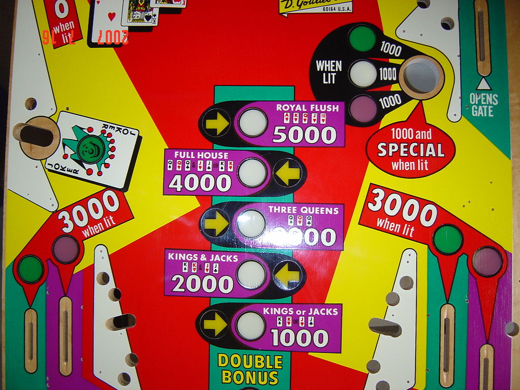
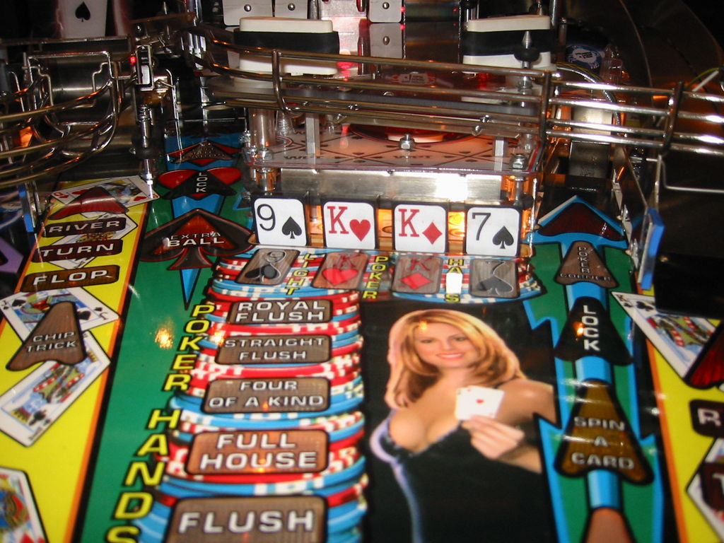
I've had an idea in my head for a while for a poker themed pinball machine. There are lots of card themed games, but much less are actually specific to poker (or any other card game). Games like Royal Flush or World Poker Tour come closest, since they involve actual poker hands, but you're still not really playing *poker*. In most EMs with poker hands, your real goal is really just to get as many drops as possible. In WPT too, if you just keep hitting drops randomly or even ignoring them, you'll just accrue hands.


So I want to have a game with a ton of targets, and a display (either dot matrix like WPT, or an LCD like Full Throttle, etc) in the playfield to show your hand, including suits, etc. The targets you hit become your hand, your hand is compared to your opponent's hand, you can bet/raise/fold somehow, etc. Not sure exactly how the rules will work, but that's the goal.

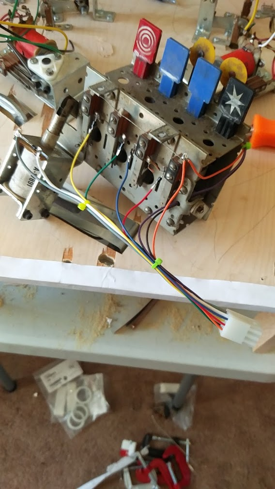
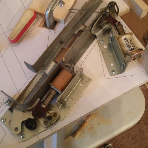
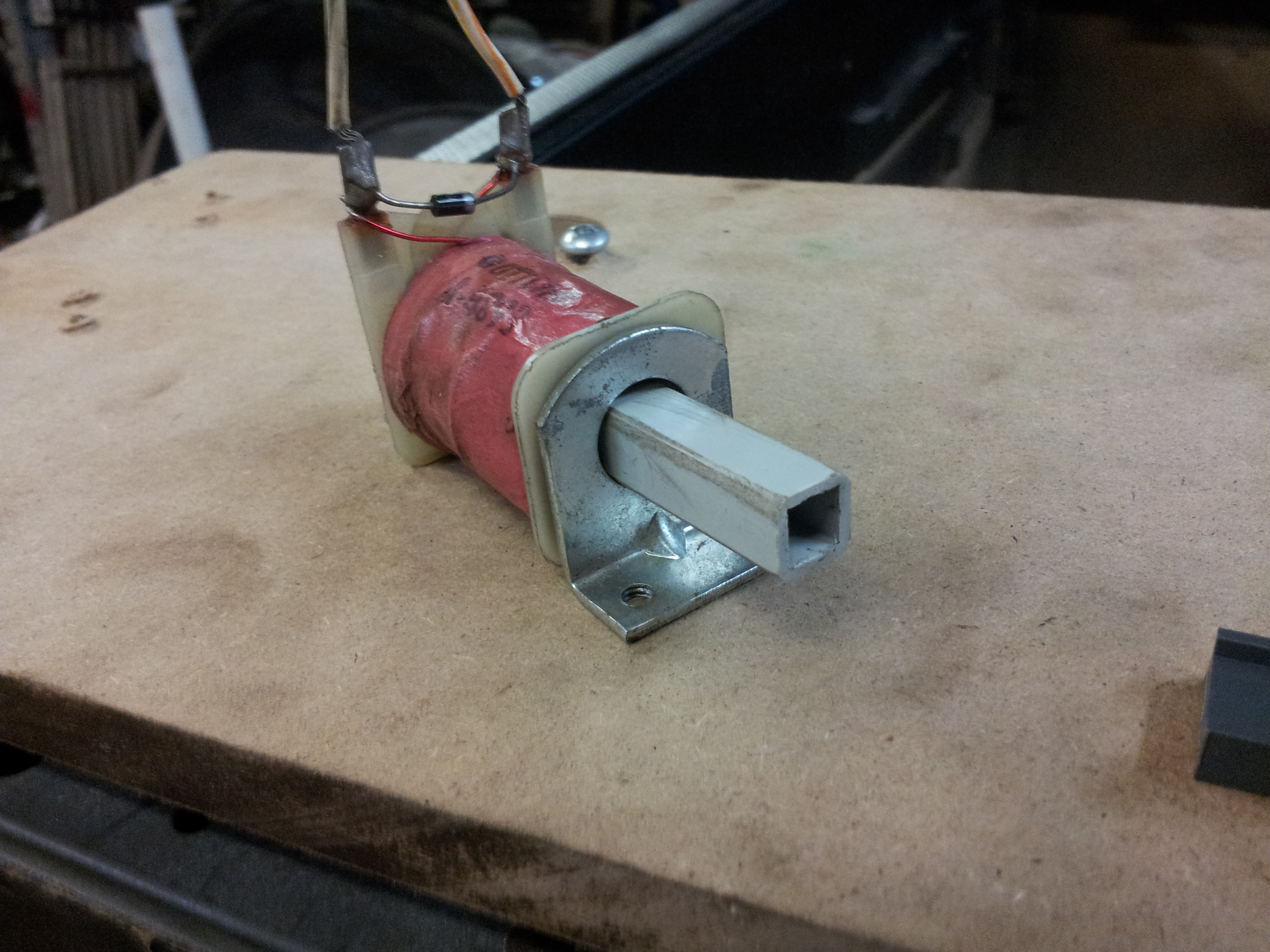
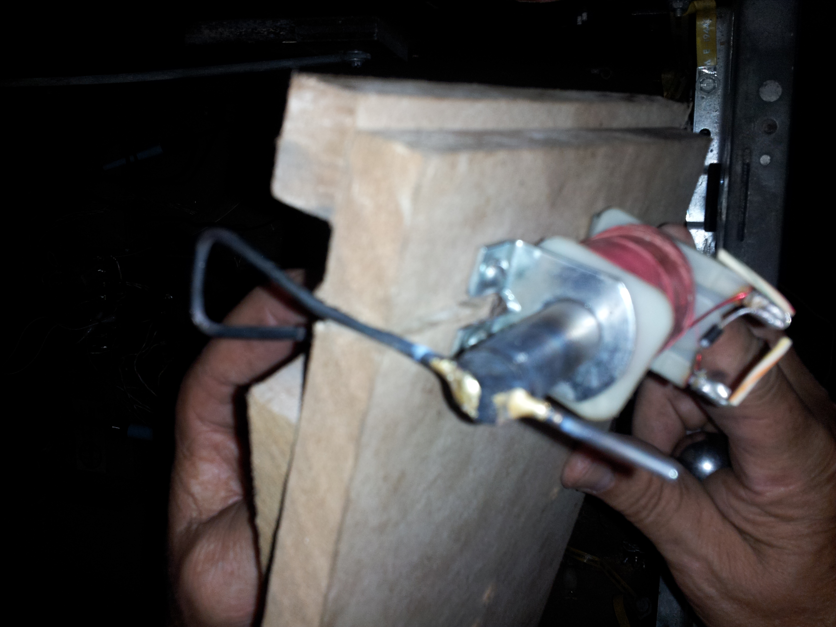
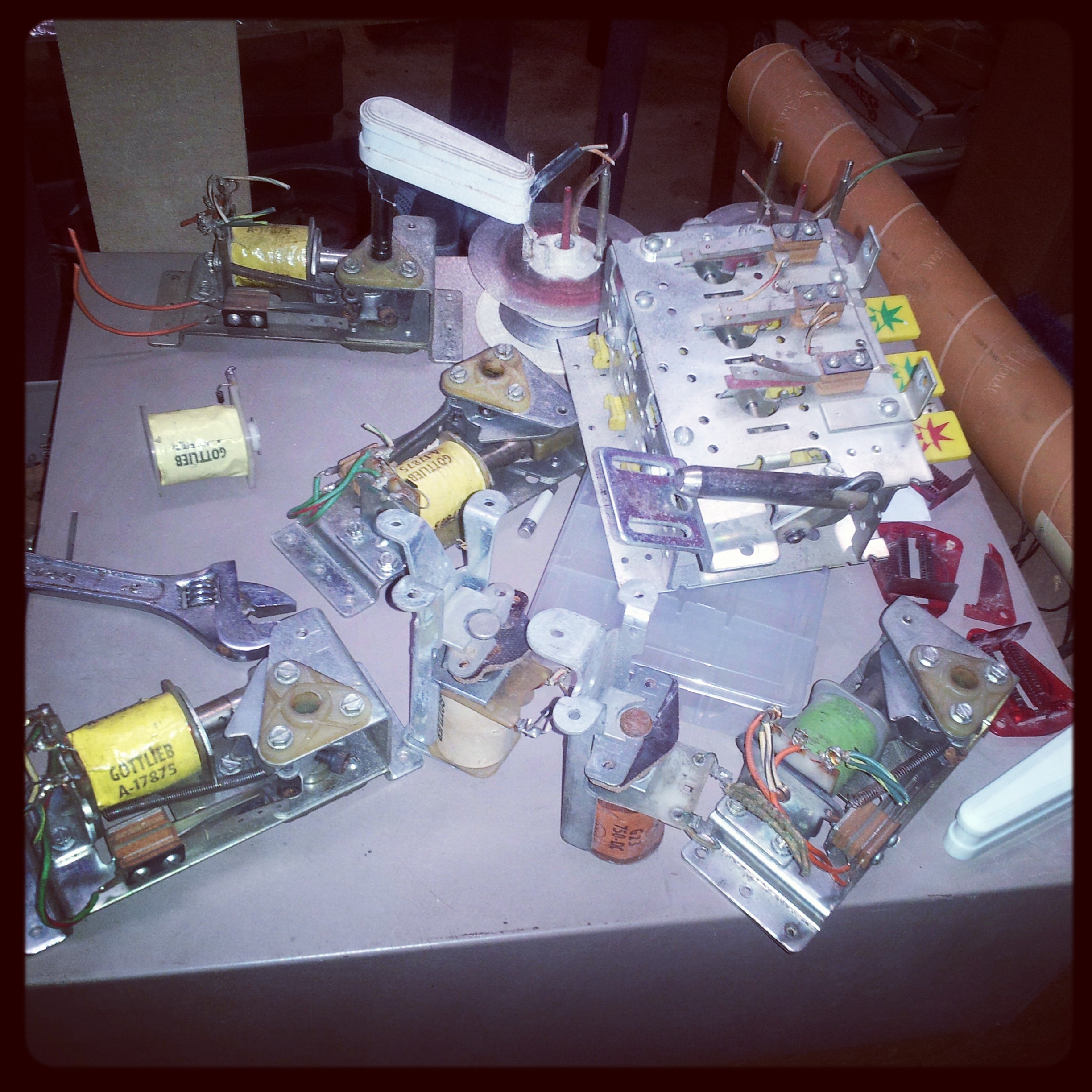
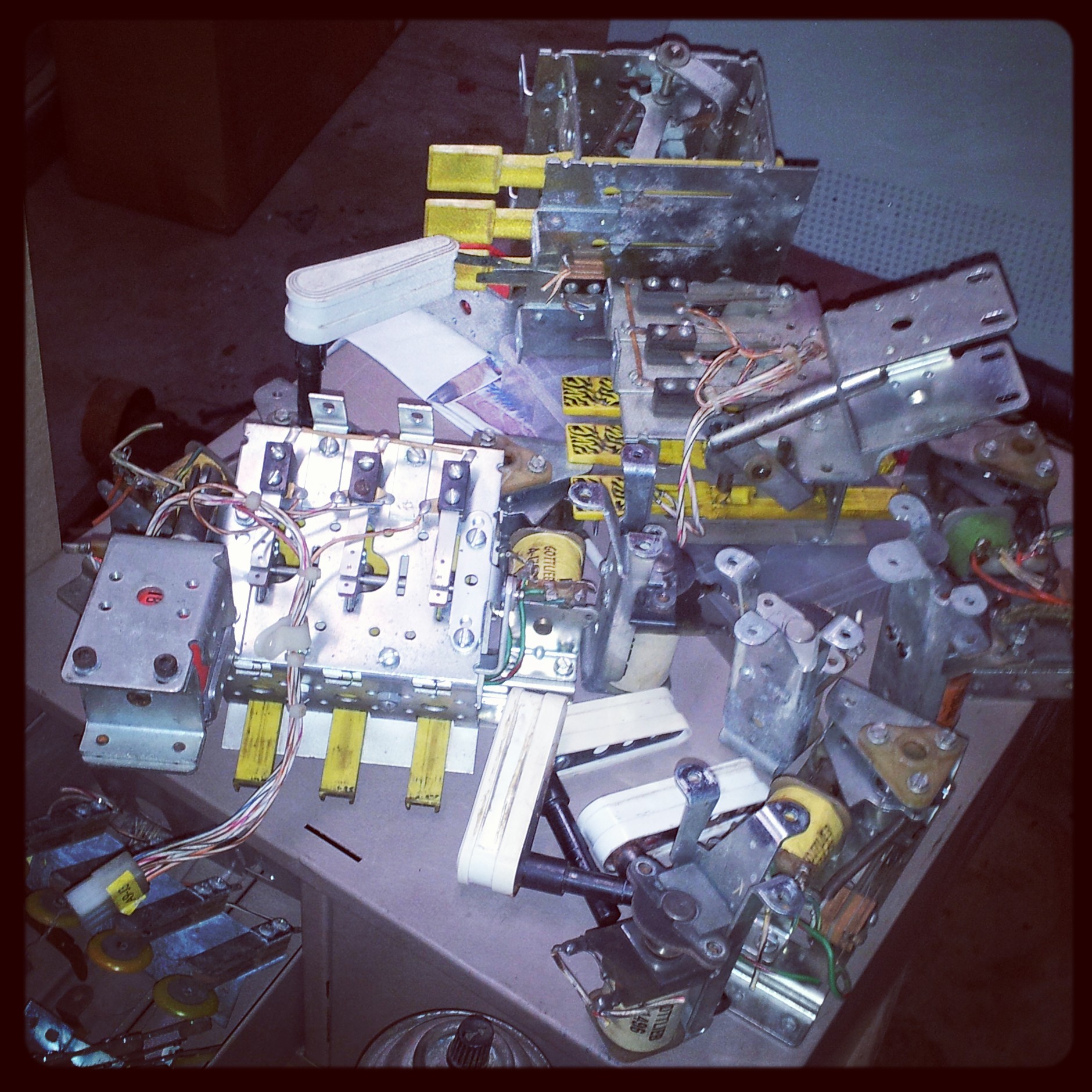
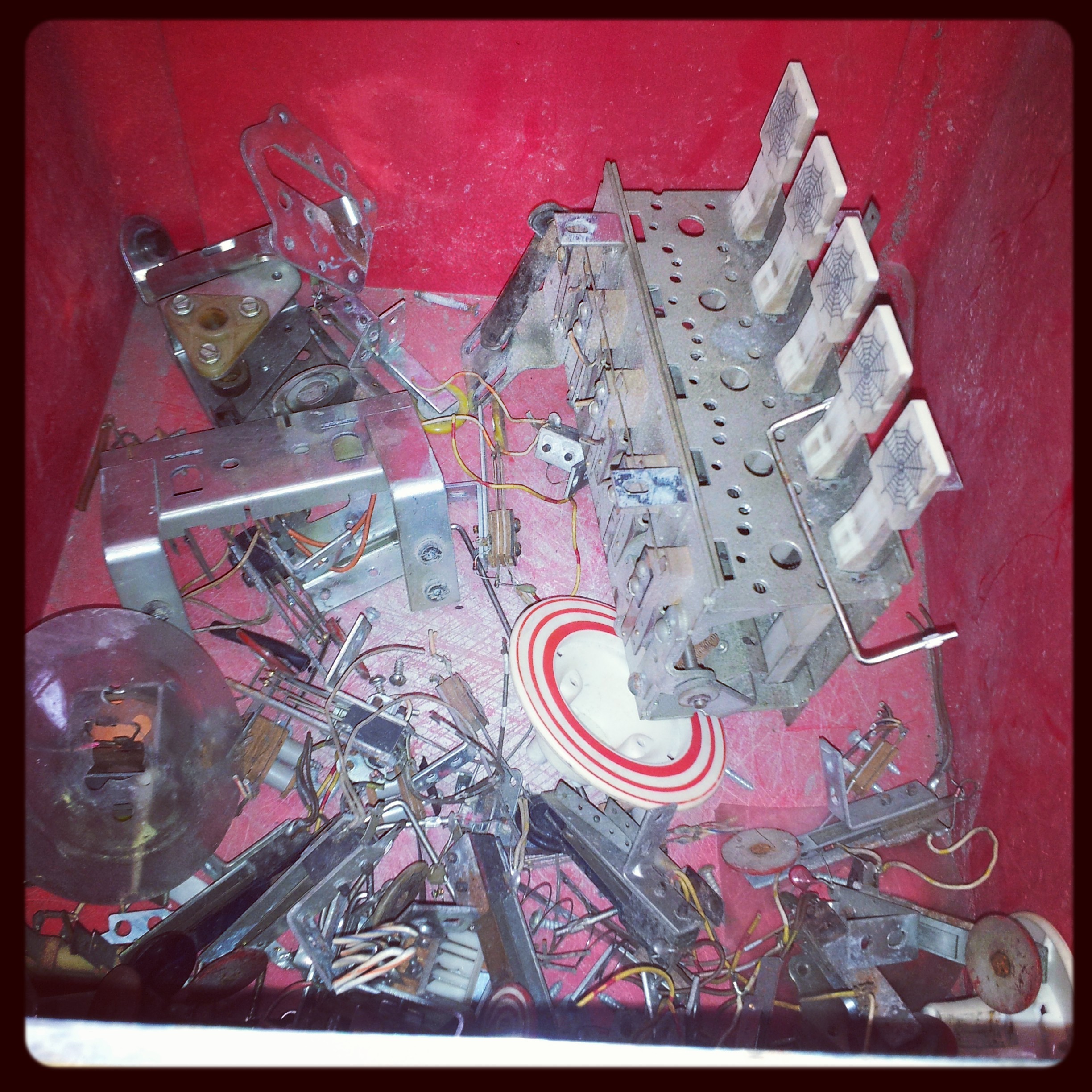
With that in mind, I've been accruing random drop target assemblies (since drop targets are always better than standups!) for years at various flea markets. I've got about 18 assemblies to choose from now, ranging from 1 banks to 6 banks. Gottlieb, Bally, Stern, Williams. Some have individually controlled 'memory' drops. Other mechs and random pieces too, such as flipper parts, slingshots, pop bumpers, gates, etc.

I didn't really have an exact layout in mind, other than having an upper flipper or two, to give more ability to hit targets, and that I want to have some sort of 'savers' in the outlanes (like magnasave, etc) since outlanes suck.

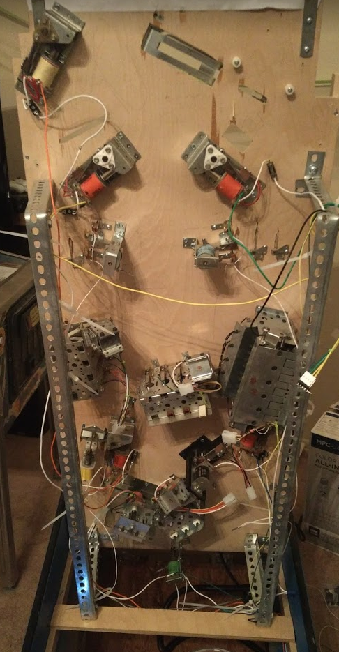
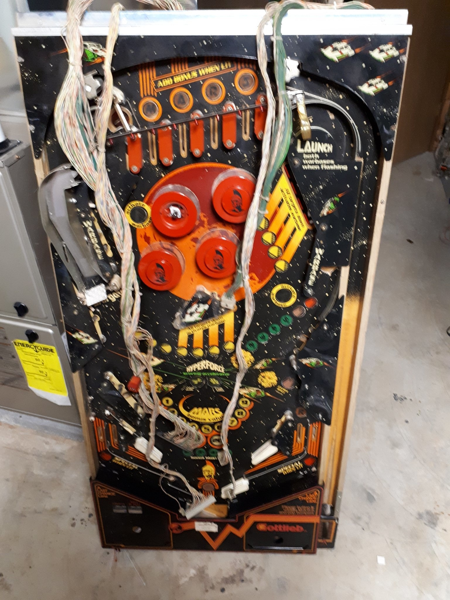
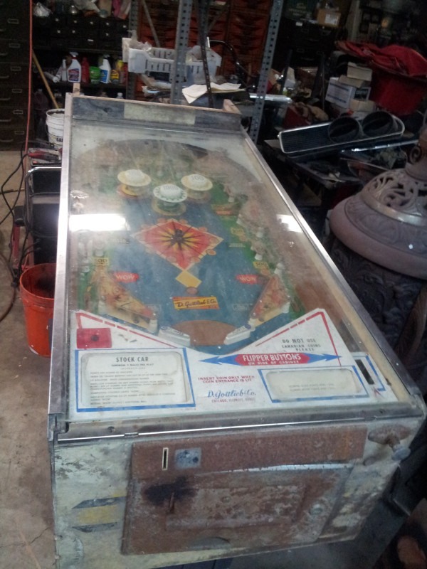
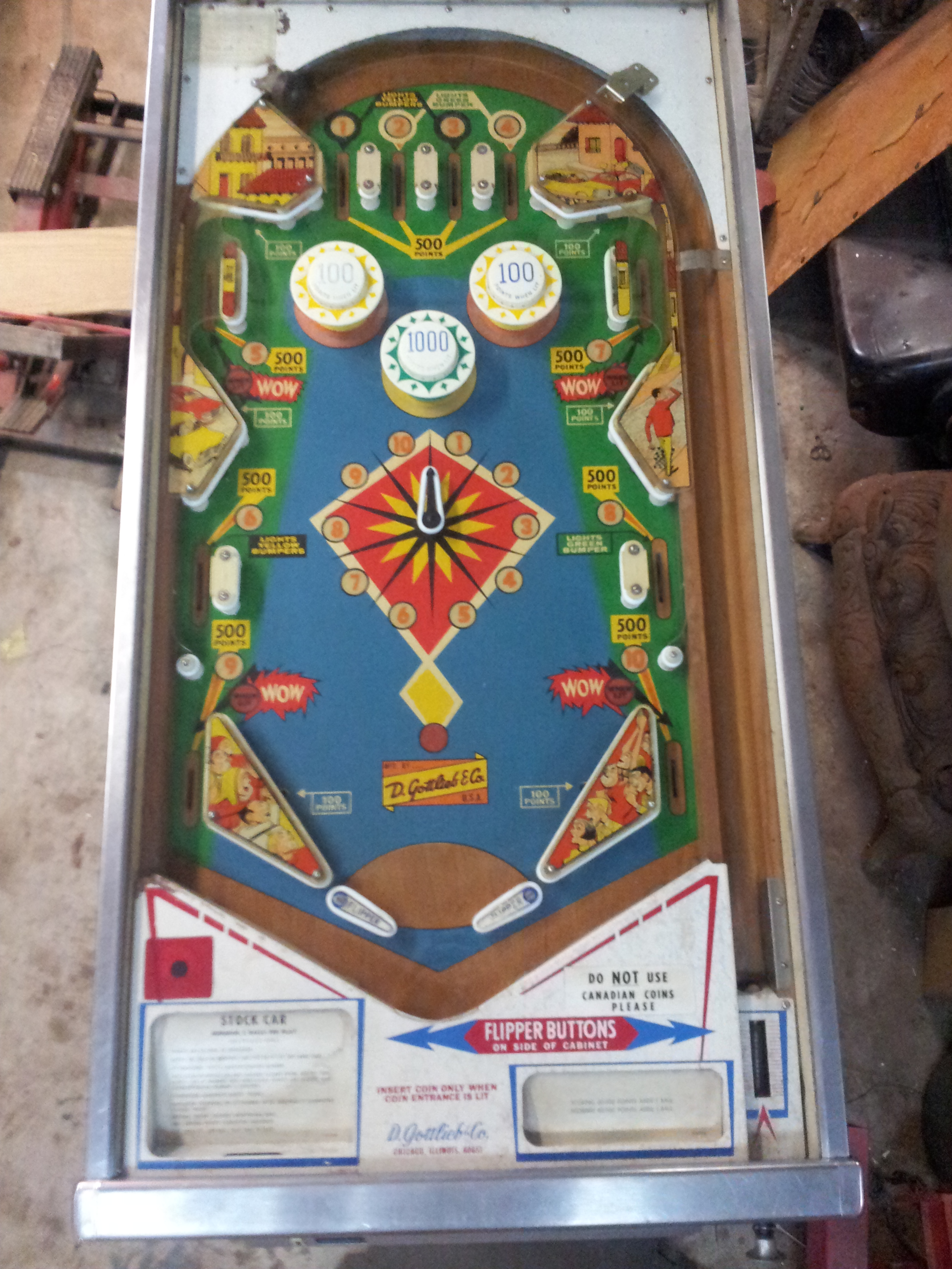
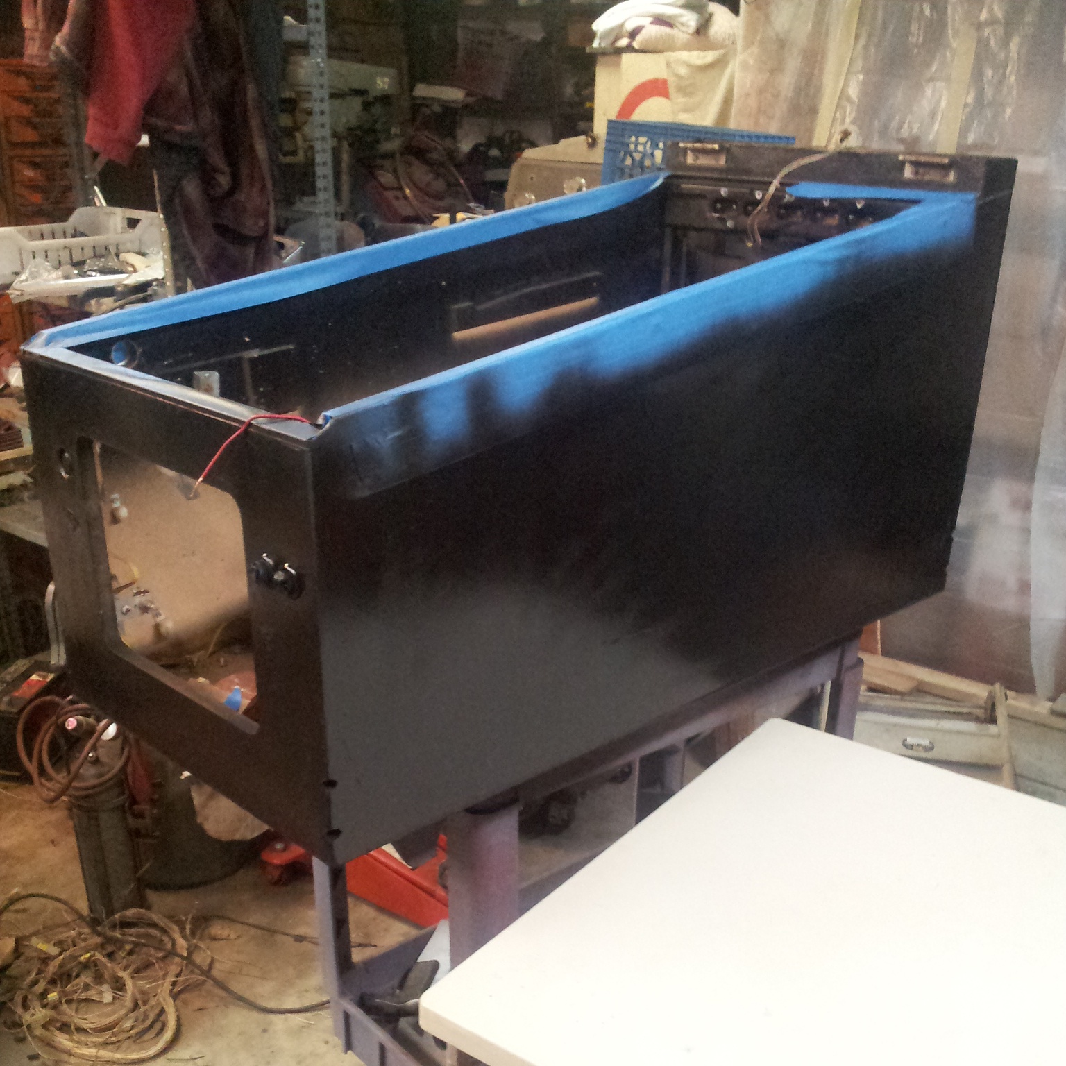
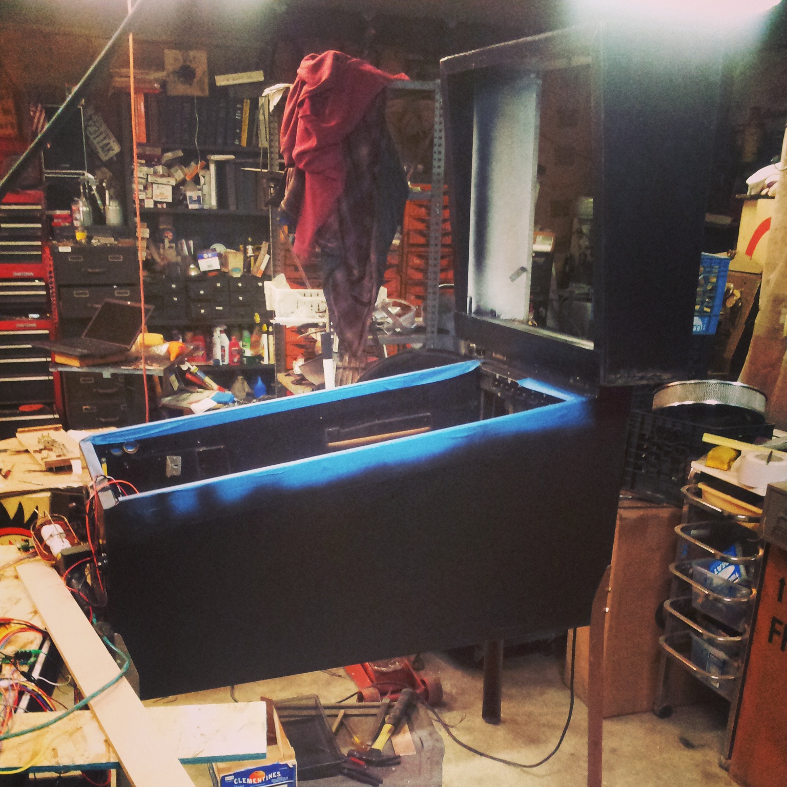
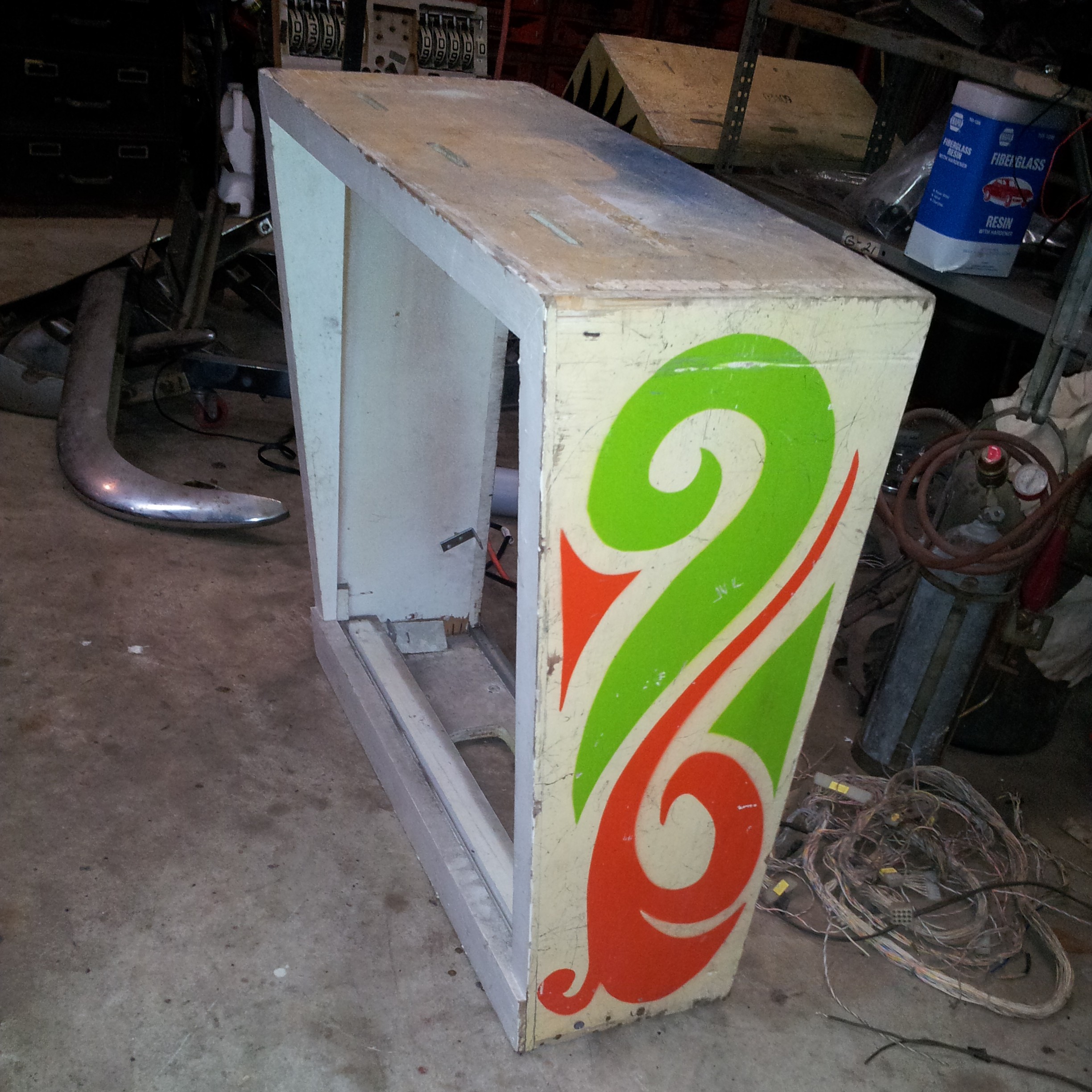
None of this ever got anywhere until I saw a partially populated Mars: God of War playfield for sale:

This had a few very important things on it:
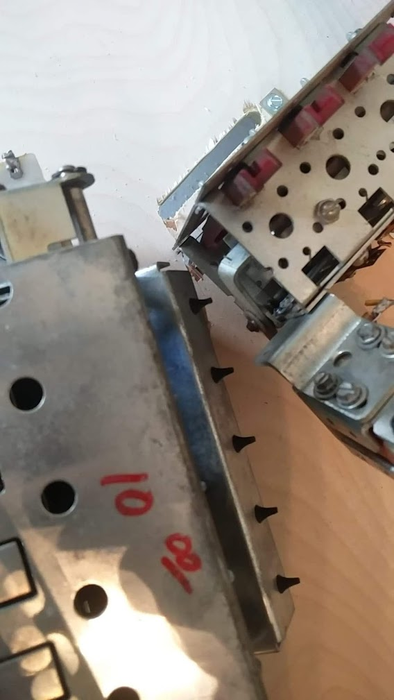
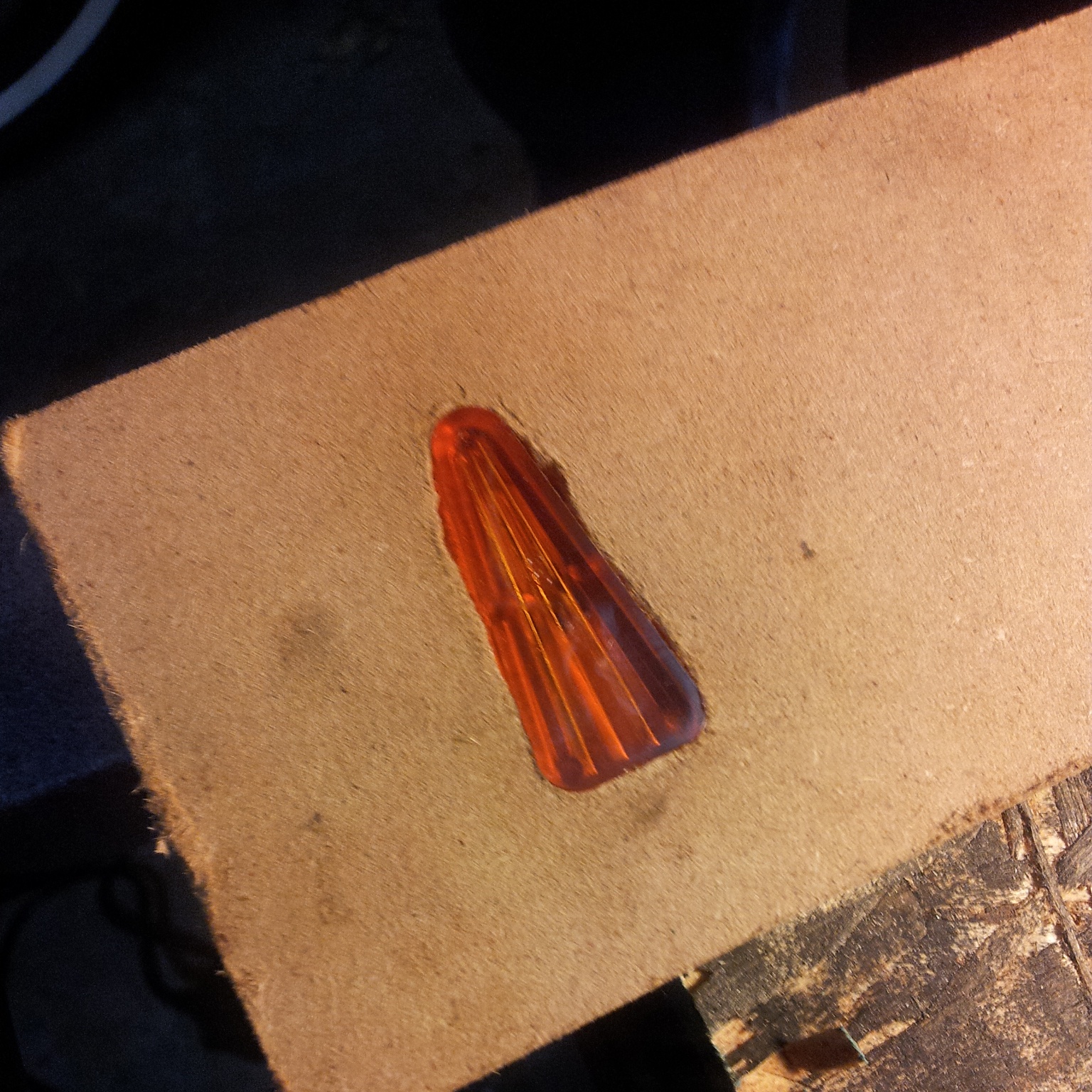
1. more drop targets. can never have too many
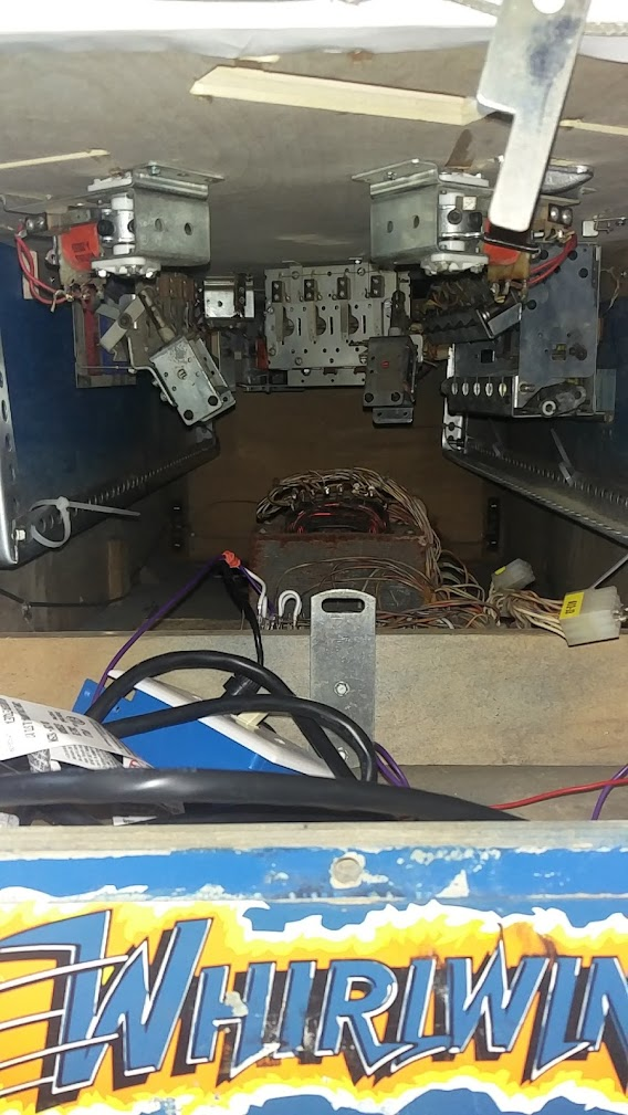
2. a multi ball trough. No need to spend $100+ on one from PBL
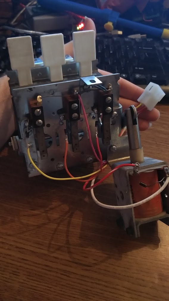
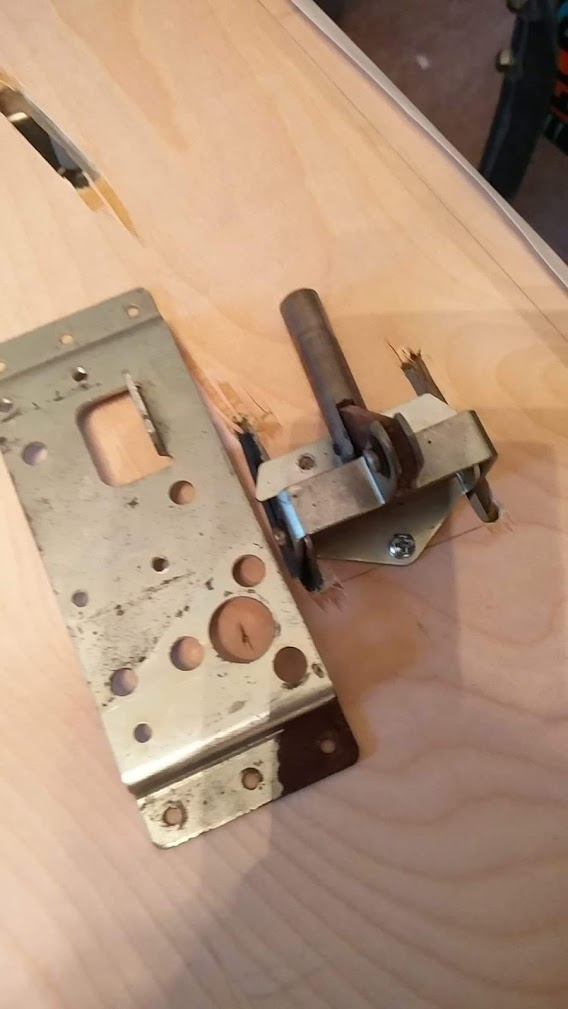
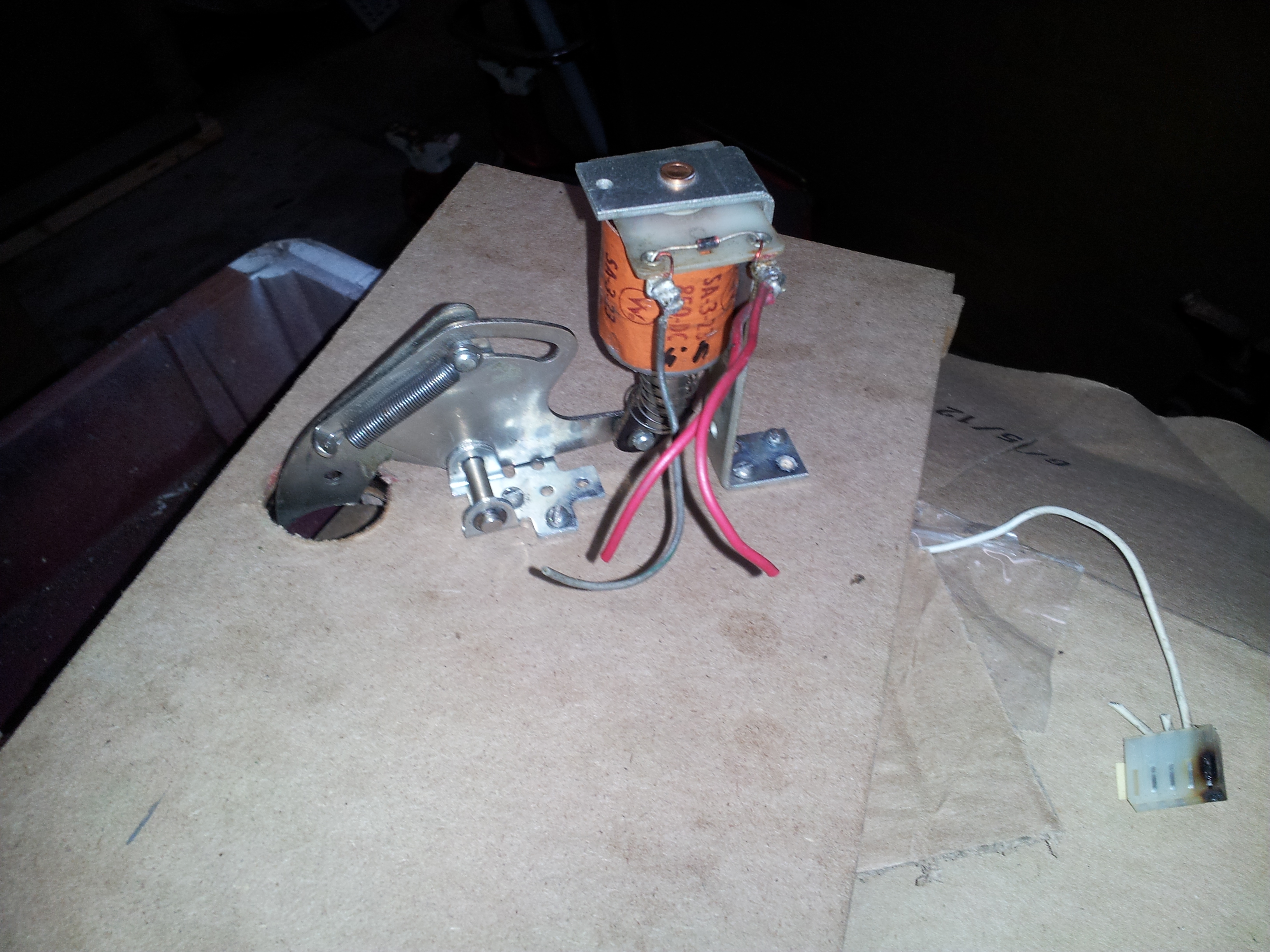
3. four flipper mechs. The WPC mechs I'd use otherwise are $50 each, but these would just need a slight rebuild, and they're gottlieb mechs, which are my favorite type, and will fit well with the more 'retro' style design all the drop targets will be giving
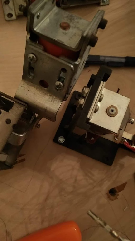
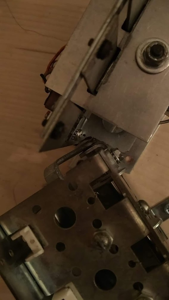
4. The lift ramp. This is what really set me off to actually start designing. I immediately started picturing layouts involving the ramp, and how I could use it as a lock possibly, or use the up/down as a diverter to give more shot variety, etc.
5. Lots of other little playfield parts. Hopefully I can scavenge lots of rollover switches, wire guides, etc. Those add up fast when you're buying new too

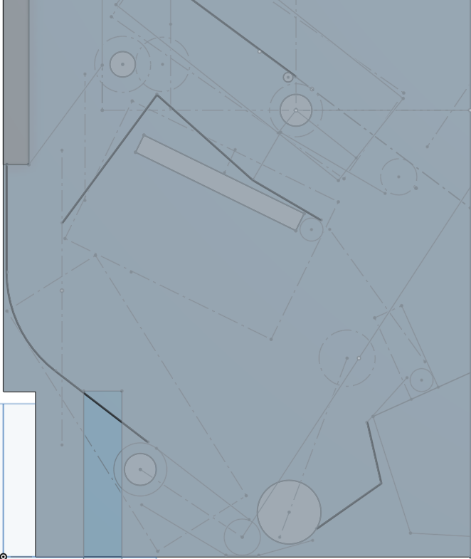
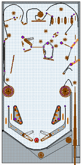
I threw out my previous idle layouts in Future Pinball and started making a new one with the ramp in mind

Old design:

Future Pinballis great for seeing how big things really are. When I sketch something on paper or in my mind, stuff enver actually ends up the right sizes, so using a virtual pinball designer is a great way to get a rough idea before you start really drawing stuff in CAD.

The first attempt was very rough, but it gave me the basic idea of a ramp on one side, a spinner on the other. A 3 bank in the middle, and above it some pops and an 'upper'/mini playfield area with another flipper and some more targets.

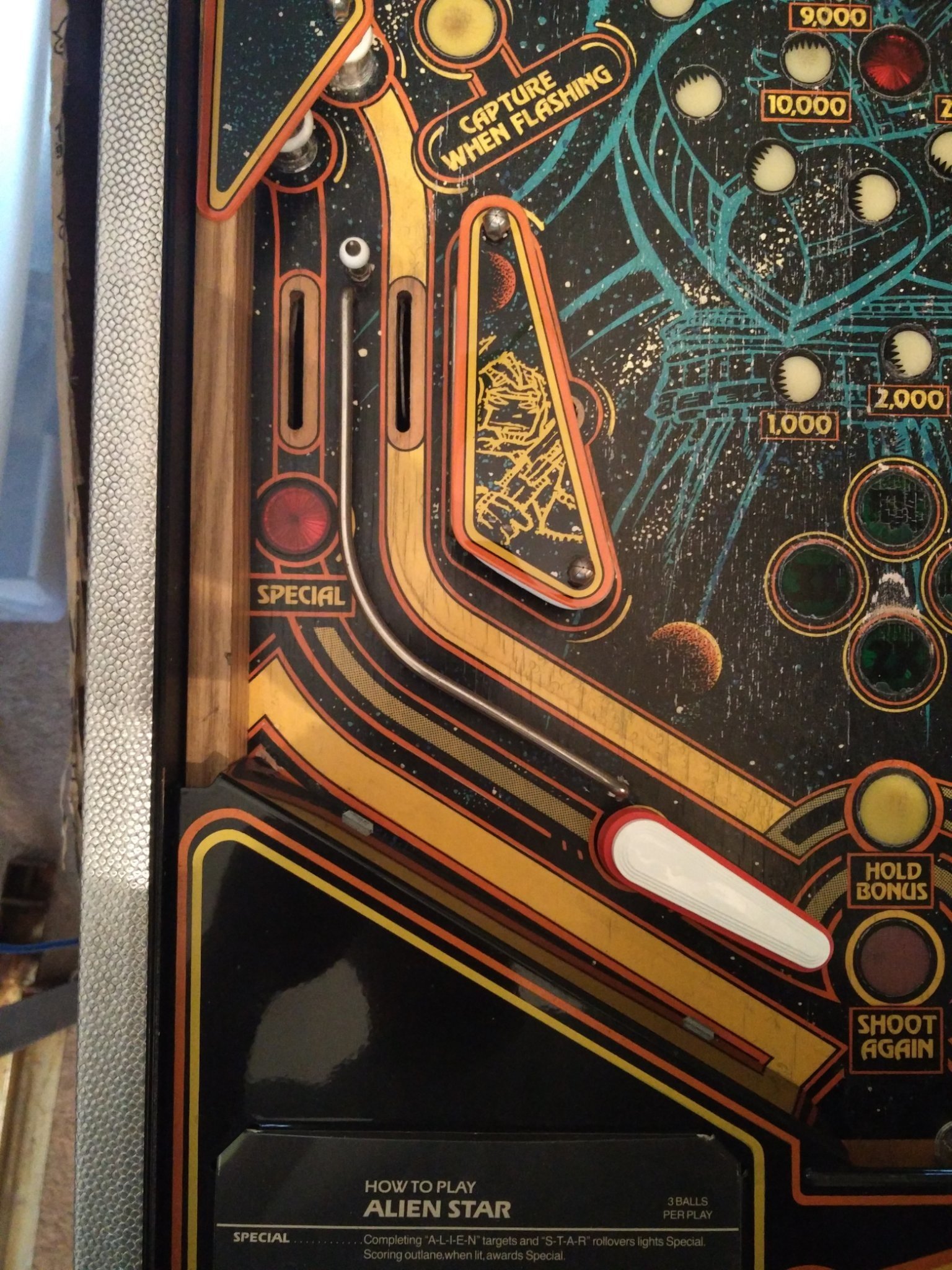
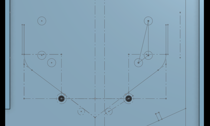
With a basic idea in mind, wanted to figure out the shot angles better. I decided to copy the bottom areas (flippers, slings, inlane) from Alien Star, since I liked the feel. This also allowed me to test out shots by imagining where they are on the alien star playfield, and then trying to shoot them, to gauge difficulty etc. One thing I wanted was a center shot that could be hit from a ball coming down the inlane when you flipped as early as possible, since I find those really satisfying. So I tried some trial shots on Alien Star, noting the angle the ball went at off that 'early' shot, and made sure to put something there in my cad drawing.

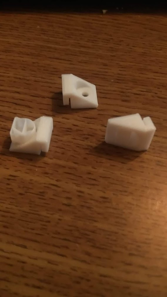
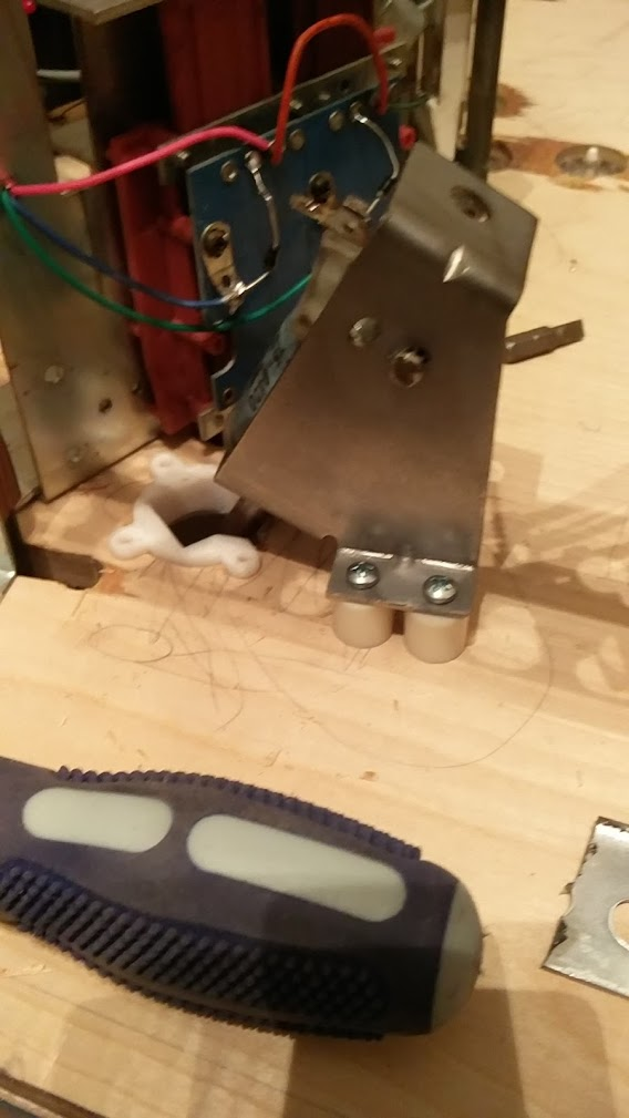
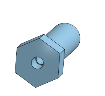
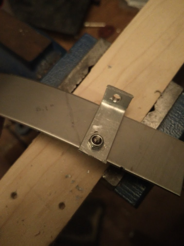
I got a cool idea for an outlane saver: a mini flipper positioned behind the main flipper, and raised high enough that you could shoot the ball over it into play:
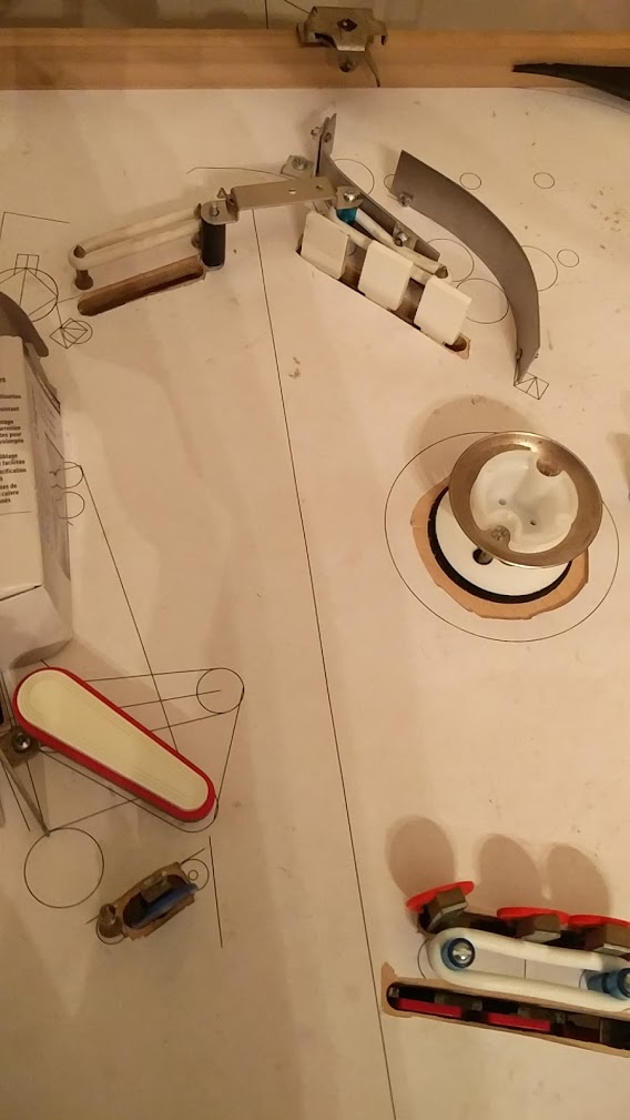
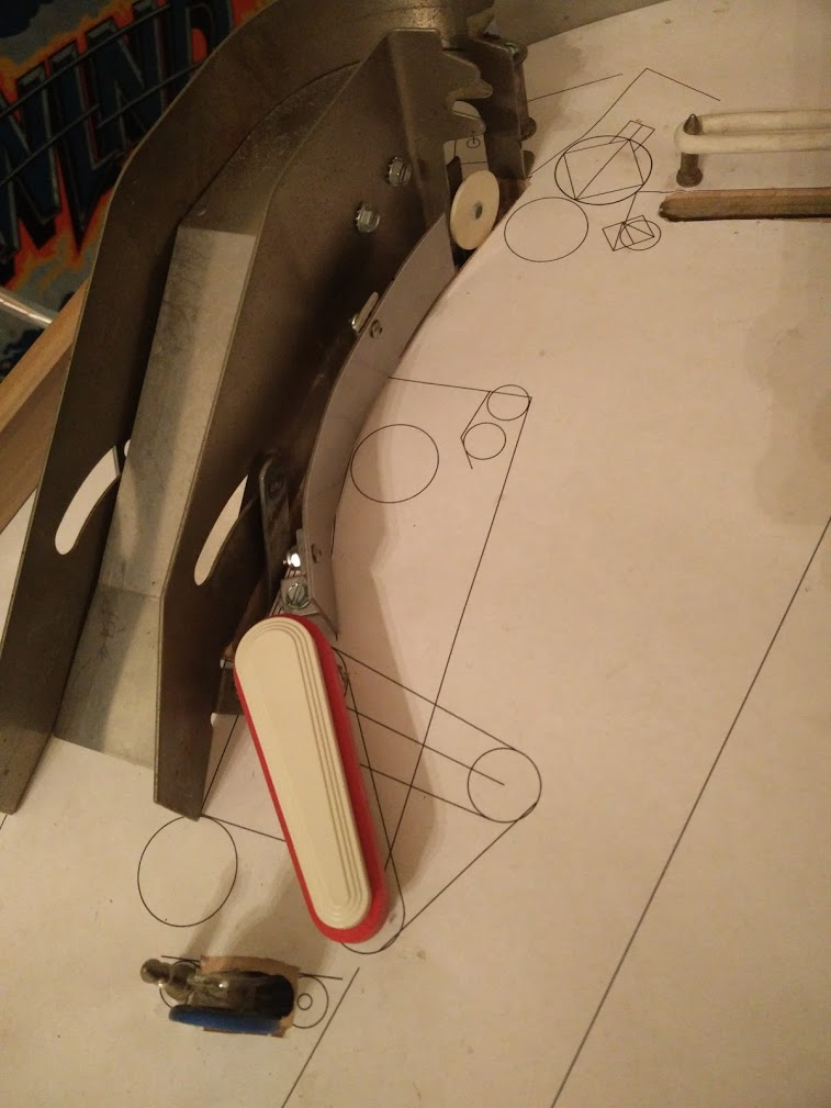
I 3d printed the feed ramp for this and stuck it on alien star to give it a try, but sadly the physics just didn't work out. The ball would roll part way up the ramp and run out of momentum. In order to make the ramp shallow enough, it would have to start about 3" above the inlane, which just couldn't work I'll have to come up with another idea for this outlane...

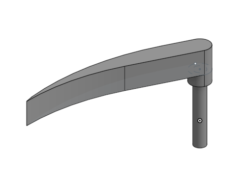
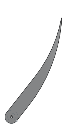
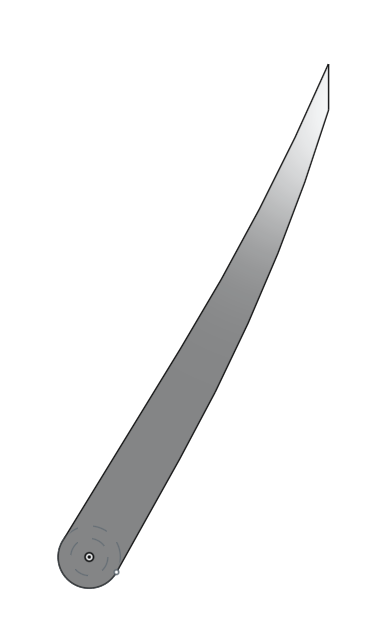
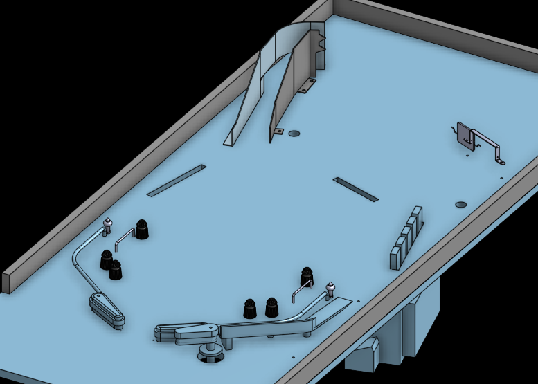
I modeled the lift ramp, which was pretty complex. I just blocked out the more complicated lift parts on the bottom, since I really just need it for spacing.
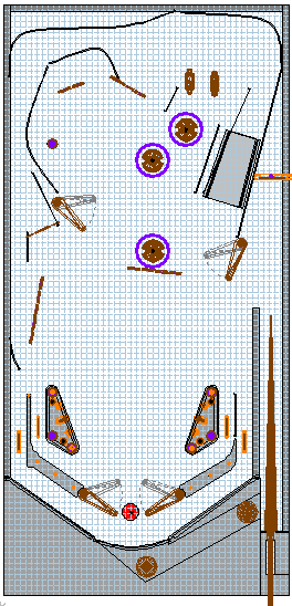
I realized that, due to the ramp's right side exit, I couldn't put it on the right side of the playfield as I had in my original drawing, so I had to reverse the playfield:

I also got more of the upper playfield figured out
- three banks down below, with possible room for a fourth under the upper left flipper.
- two upper banks, each with some targets hittable from the lower flippers and some from the upper flipper
- a shot in the middle (the 'early' shot from before) that can feed the upper left flipper
- a lane to the right of the upper right drops to go from the upper playfield to the upper right area, where there will be some lanes
- one pop bumper (that's all that will fit, but all the best games have one pop bumper!)
- a shot under the upper left flipper from the upper right. not sure where the ball will go once it gets in there yet
- a shot back to the shooter lane from under the upper right flipper, similar to Star Trek, but with drops below it, so you can hit down the drops to make the shot wider

More refinements:
- placed lots of mini targets to prevent vulnerable metal edges
- replaced the area below the upper left flipper with a single target to make the shots to either side easier
- replaced the upper left bank with standups, since sadly it looks like there isn't clearance for two mechs that close together
- added the lanes in the upper right. there isn't enough room for a full set of three lanes, so I've opted for just some mini posts to drop the ball between. the right most 'lane' will drop down to feed the upper right flipper, and there's also a place below it for a magnet to feed the flipper too off orbit shots. I wish this was a widebody, so I had more room to put stuff in areas like this, but sadly widebody cabinets are hard to come by, all I have is a narrow body

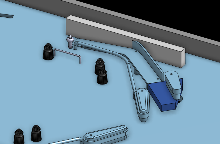
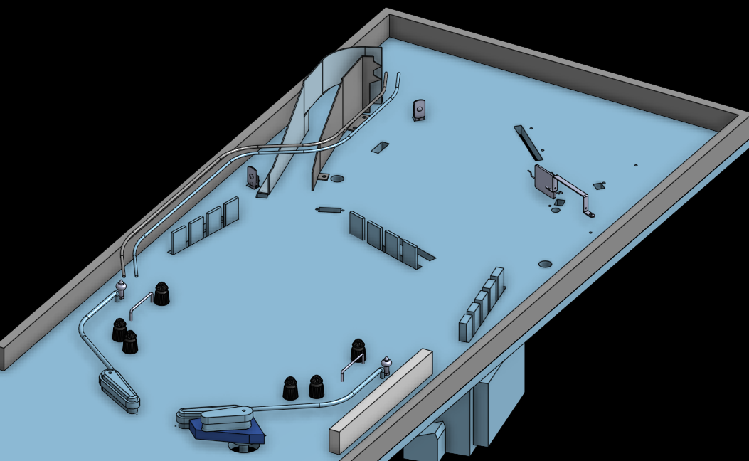
I modeled some of the drop target banks and added them, as well as a rough habitrail for the ramp

Clearances are already getting quite tight with all the mechs there.
- I originally wanted the upper left flipper to be more to the left, but the ramp lifter mech is in the way
- the upper right flipper had to be moved up slightly, since the 5 bank below it was in the way
- I had to change my 3 bank mech for a different one that had the coil on the left instead of the right

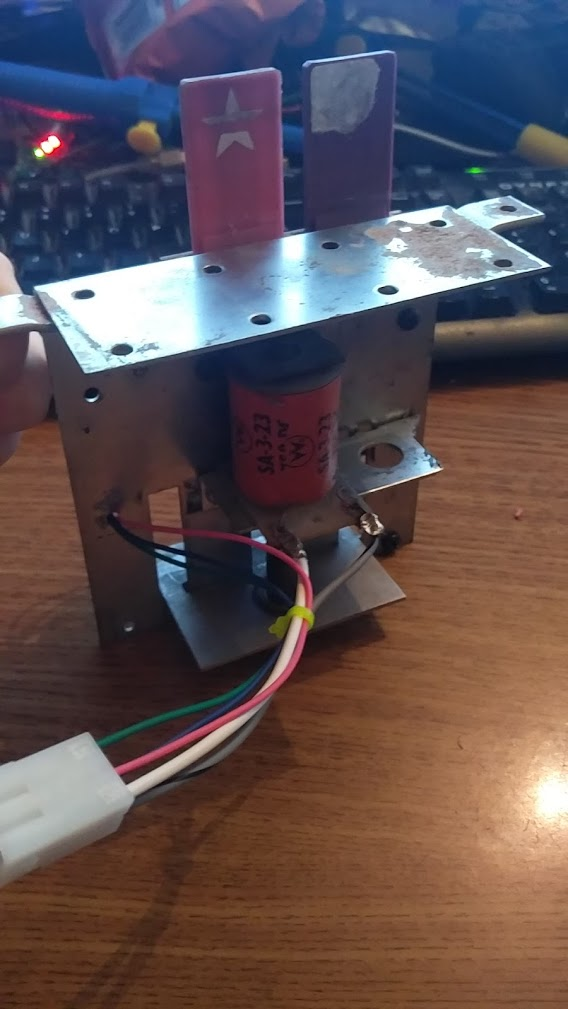
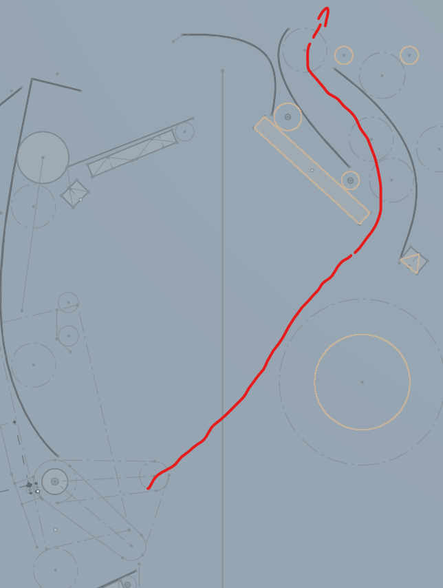
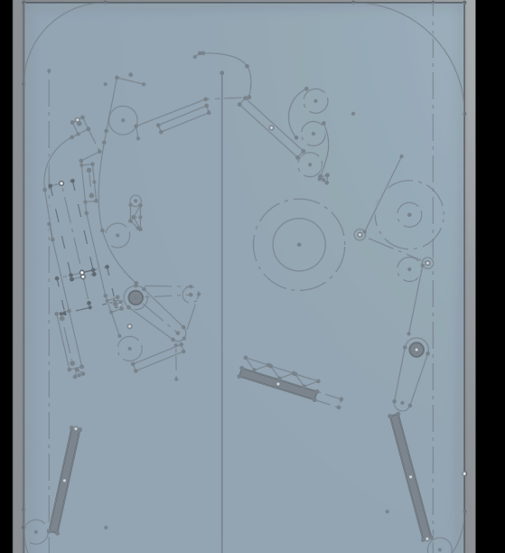
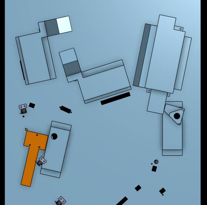
Bought some used magnets from a parted out Addams Family, which allowed to to add a magna save on the leftlane. I got an evil idea though, and decided to invert the inlane/outlane, bally style. This way, if you just hold the magnet, you can bring the ball to a stop, but it'll be above the outlane! I want to make the game more bouncy, encouraging the ball to fly around all over. Both the outlanes with have helpers of some kind like this, so it should be okay to be a bit more out of control.
The inverted inlanes also allows me to use the left side of the playfield as an inlane feed. I'll but a controllable one way gate above the upper lanes, so then a spinner shot can either feed the lanes, or come all the way around, down the left side, and feed the left flipper again for a repeatable shot.

Similarly, on the left side, I'll put a diverter in the shooter lane, so balls can either go back to the plunger, or feed the left inlane. This will allow another repeatable shot by shooting under the ramp on the left, coming around the top, and down the right side. Hopefully this will give some good combo potential (especially combined with the lowered ramp to feed the left side, to give the game some shots and modern feel, despite most of the playfield being taken up by drop targets

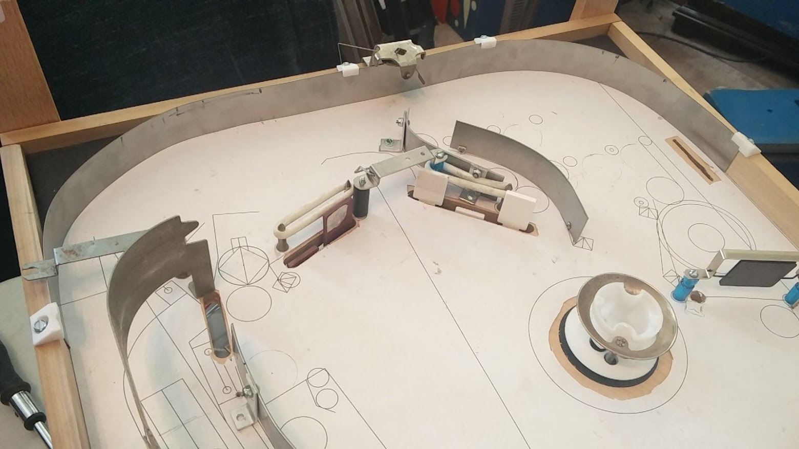
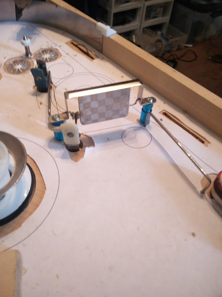
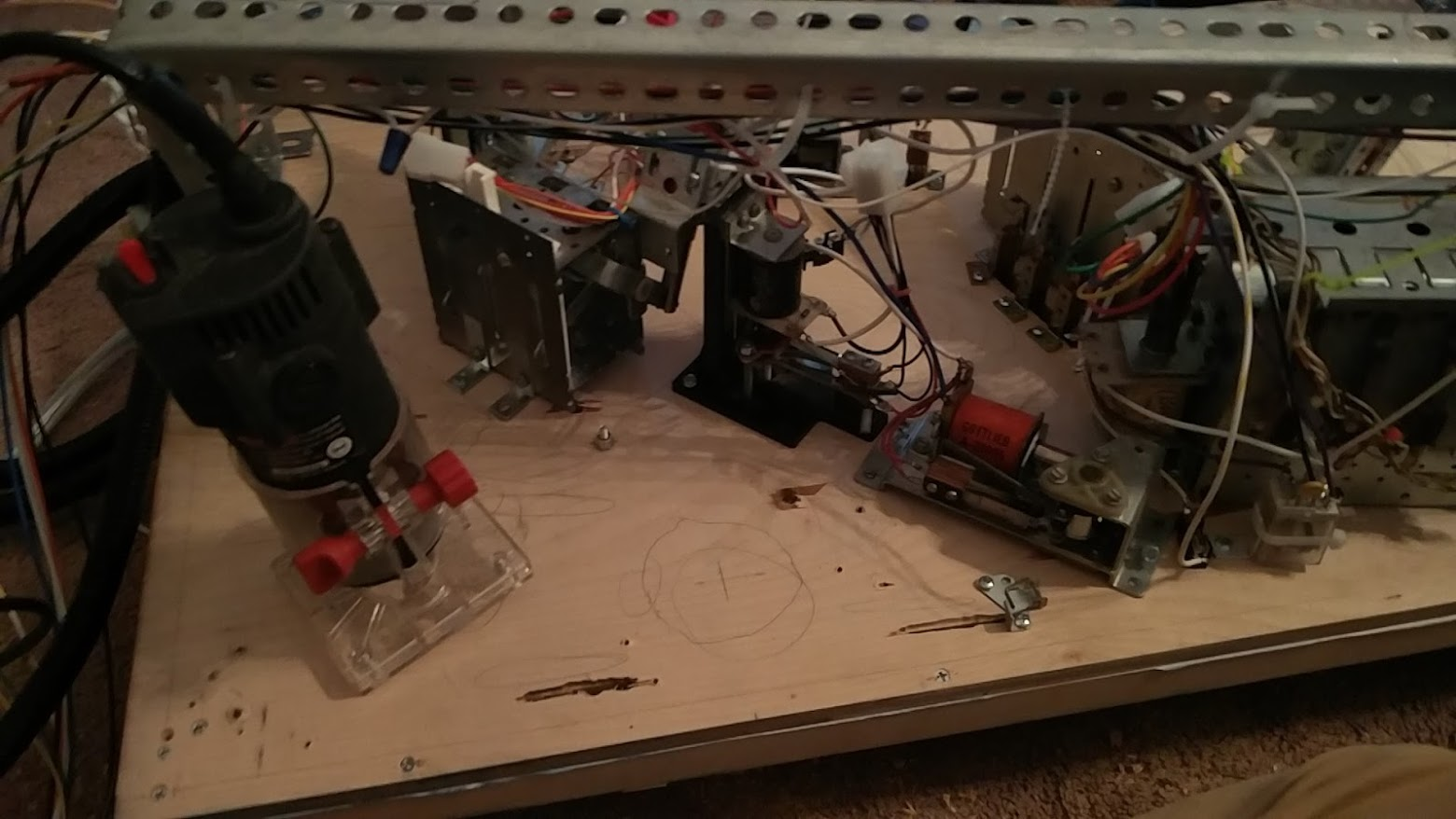
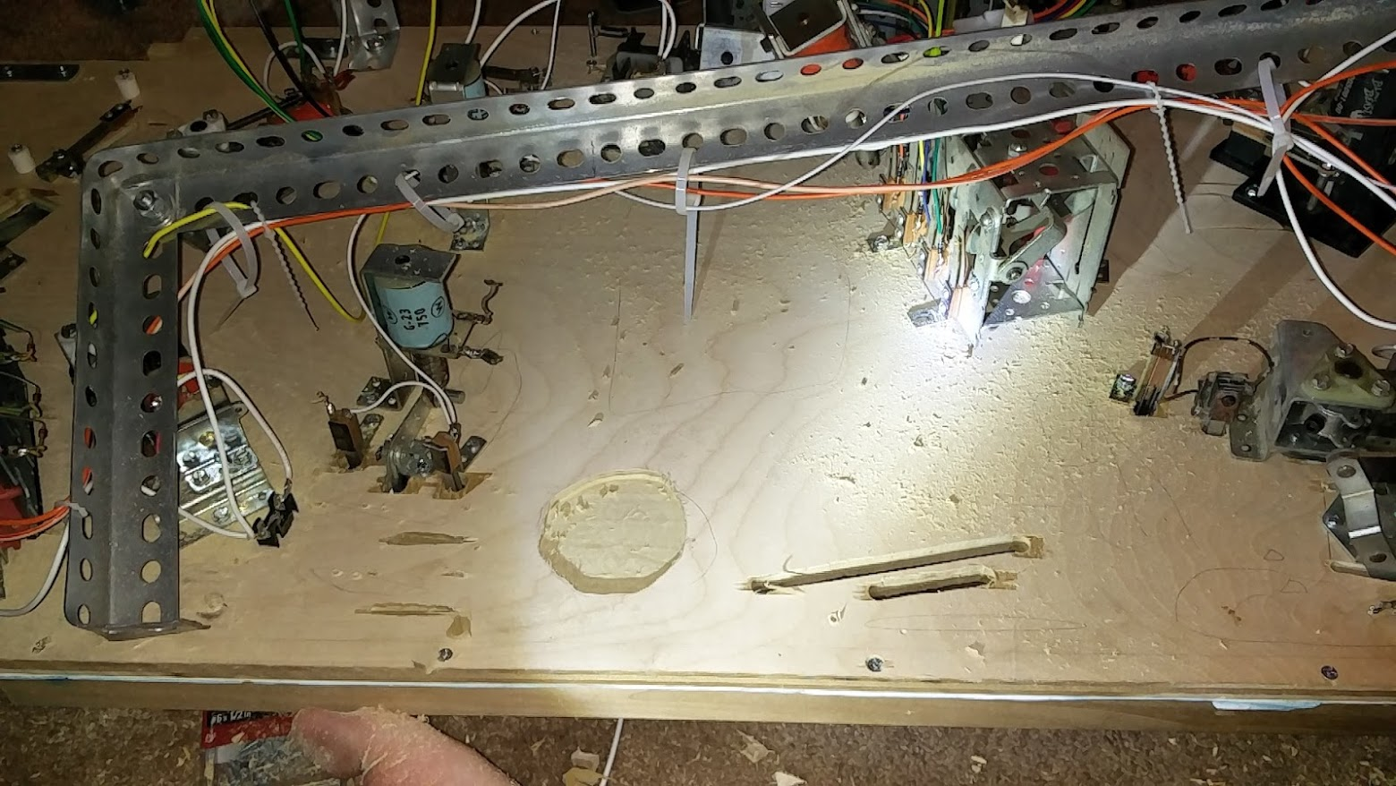
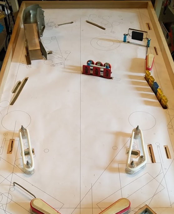
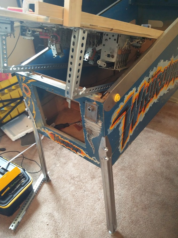
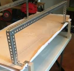
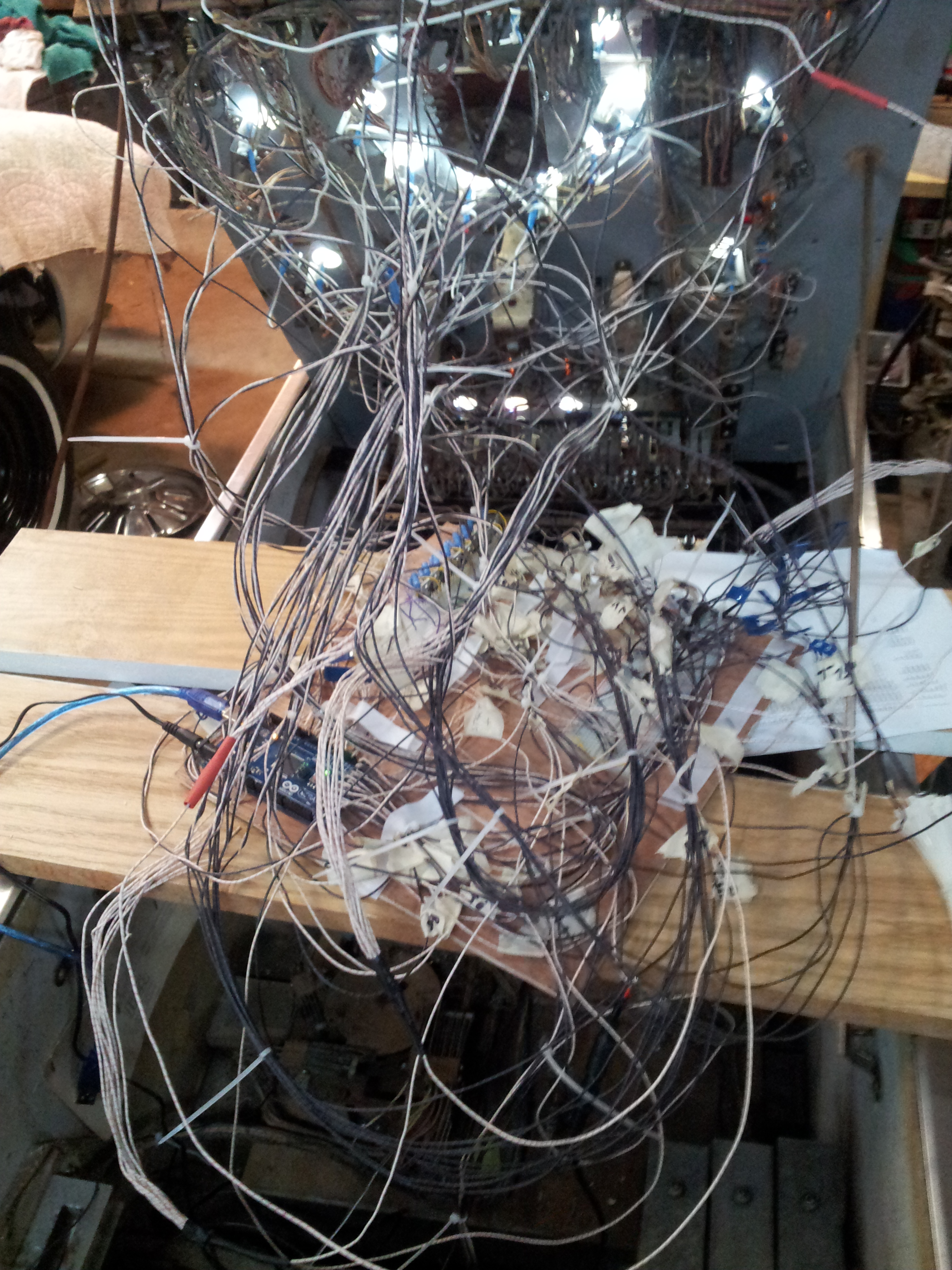
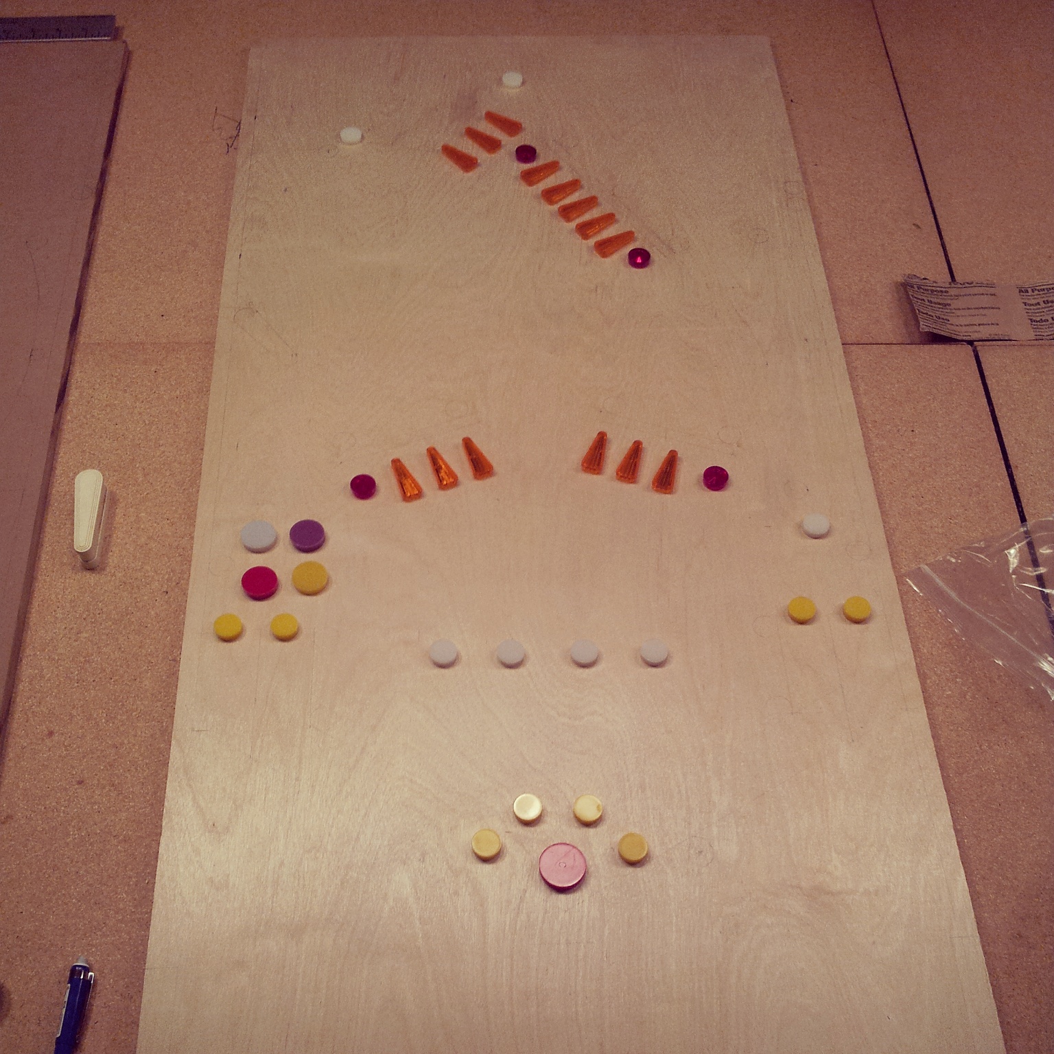
At this point I start to worry I'm getting ahead of myself. I don't even have a whitewood yet! There's no reason to be putting this much detail into a design that could change drastically if something doesn't work out. So it's time to do a whitewood. I won't install everything yet, but at least get some guides and flippers installed, see how it shoots.

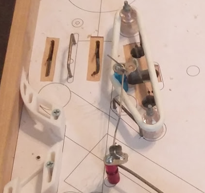
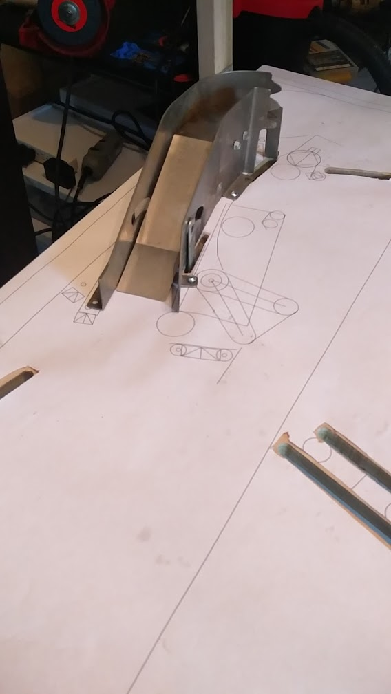
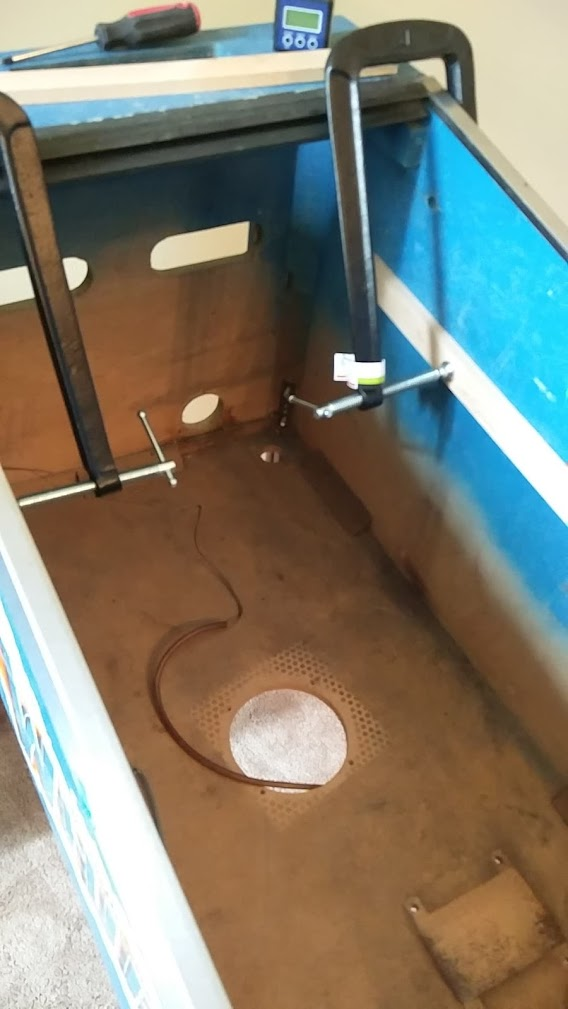
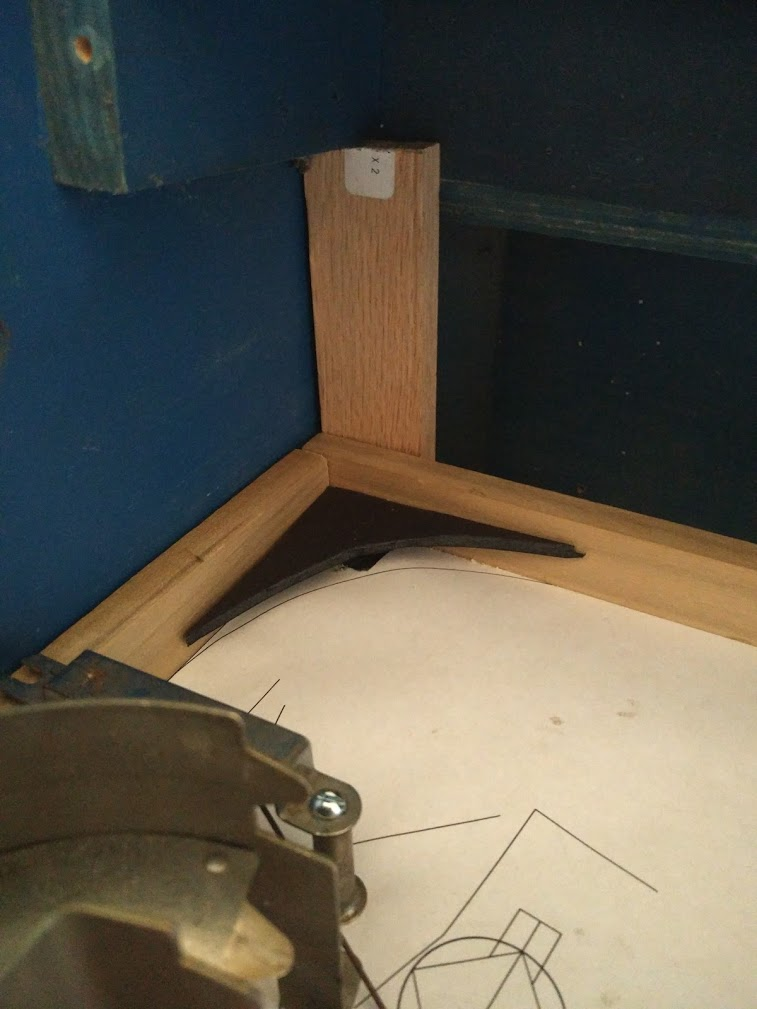
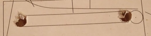
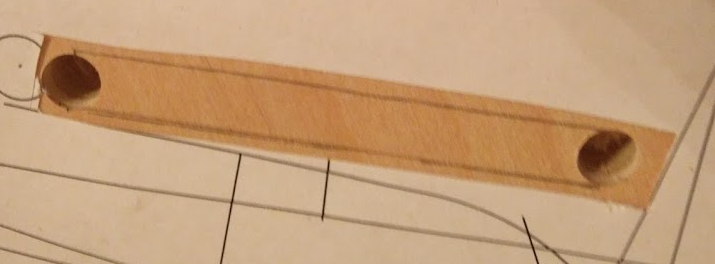
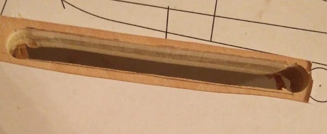
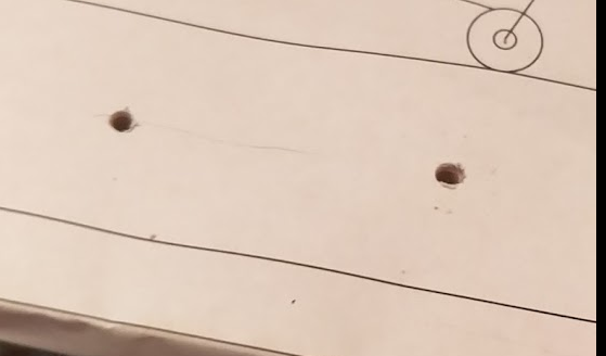
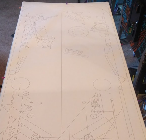
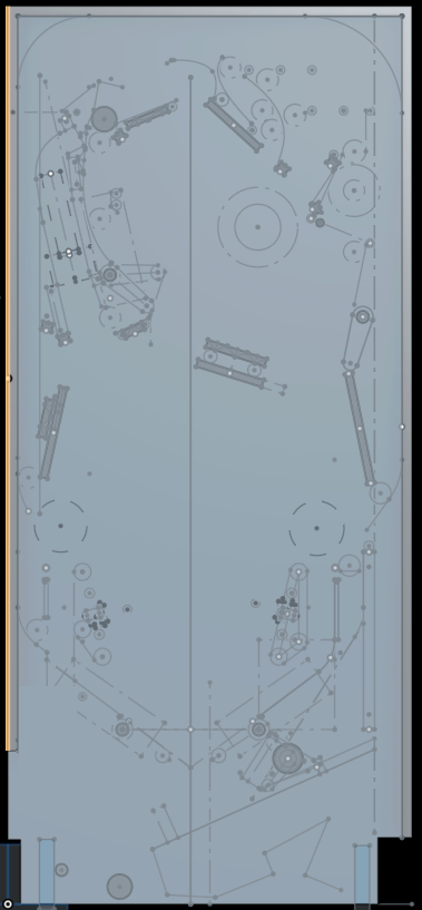
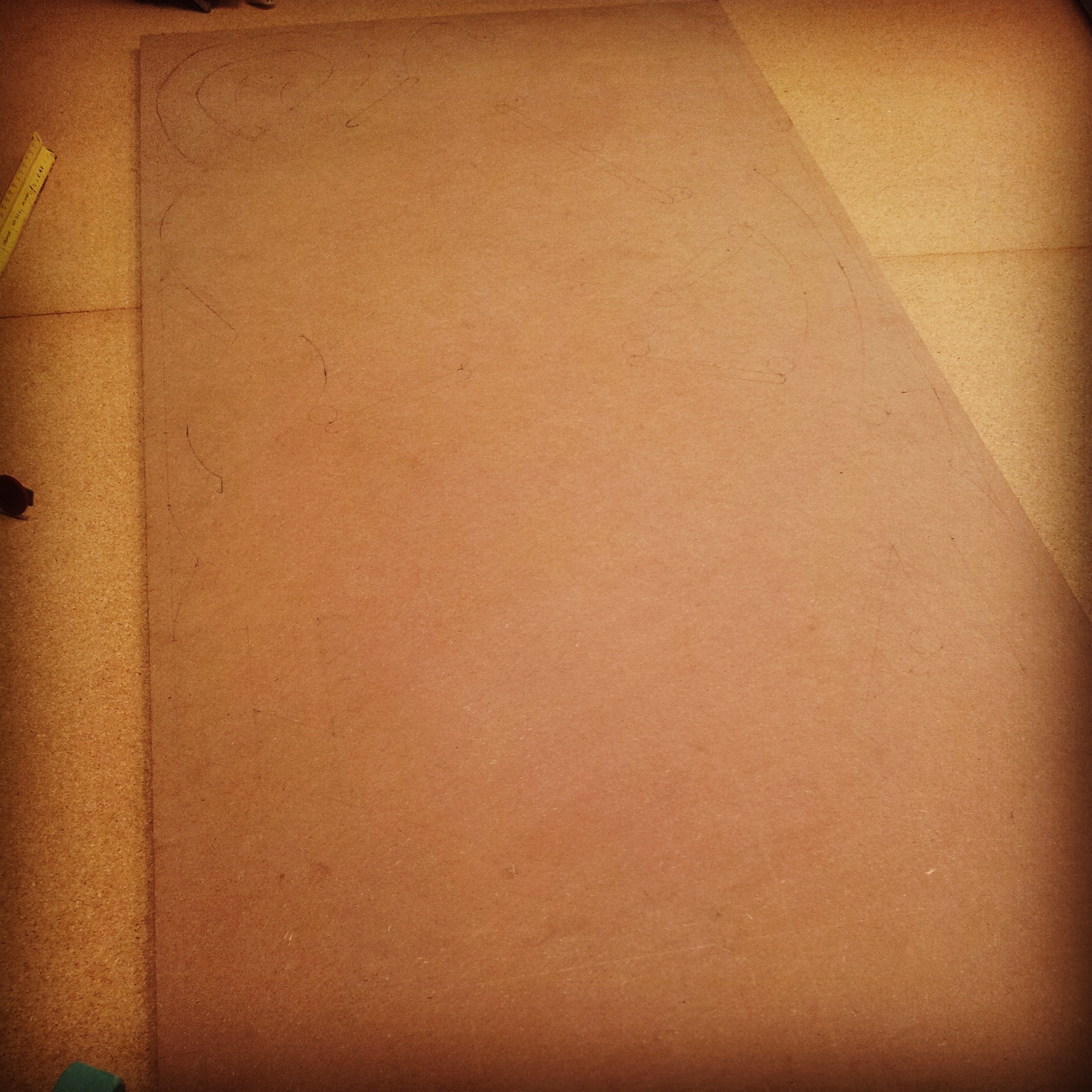
I don't have access to a CNC machine, so I'll need to do this all by hand for now. I take my current drawing and send it to Staples to get printed at 1 scale. My thinking is, I'll attach the paper over the playfield, and use that as a guide to cut all the holes needed. Hopefully I can play test on paper without ripping it up too badly.
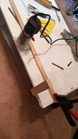
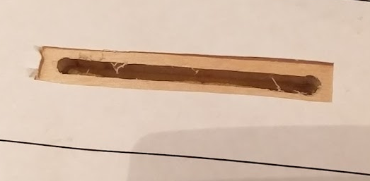
Tomorrow, the first steps of construction!

Posted Tuesday, September 08, 2020
at 08:54 PM


Tags: Blog Post, Pinball, Project, P3,

Stern Dracula Tournament Rom V4

I've been working on a custom ROM for Stern's Dracula for a bit now. This was originally prompted by wanting to remove its 5x bonus rule. In the original ROM, there was no way to earn 5x. You could earn 2x bonus, but 5x could only be gained by random luck on the last ball, when it would alternate between 2x and 5x (once 2x was earned) when the slingshots were hit. This made it very bad for competition play, as a 5x bonus collect could often eclipse whole game scores.

After removing that rule, I decided to make the 5x earnable by the player, and then made some other tweaks to try to rebalance the game now that 5x was in play:

  • 5x alternation removed
  • 5x achieved by earning 2x bonus again after 2x bonus is already lit (eg, by completing the left 3-bank of drops twice and shooting the loop three times)
  • to make this a bit harder (since getting 5x should be harder than getting 2x twice), once you earn 2x bonus via either method, the other method resets (loop resets to first star, or 'light double bonus' light at left 3-bank turns off if it's on)
  • made the extra ball worth 25k points, and made it collectable multiple times per ball
  • lowered the special score from 100k to 70k (still playing around with this value to try to keep it balanced with the 5x bonus)
  • X-Y-Z target progress carry over from ball to ball (per player). Once special is lit, on the next ball you need to hit the Y target again to relight it.
  • free play
  • sped up 5x bonus collect

If anyone would like to test this or has any further suggestions, send me an email

Posted Tuesday, January 15, 2019
at 09:23 PM


Tags: Blog Post, Pinball, Project, Dracula, Custom ROM,

Custom Bally OS, Pt 3: Lamp Control

Many months later I have picked up a nice Stern Dracula pinball machine, which allowed me to actually go and start testing this code in a game and get working on the I/O support.

Bally has an interesting system for driving their lamps. Unlike Gottlieb (who just had one transistor for each lamp and banks of latches to remember their state) or Williams (who used an 8x8 switch matrix), Bally opted to use 60 individual SCRs. SCRs have an interesting property to them: unlike transistors, which allow current through when there's voltage at their input and then cut it off when the input turns off, SCRs will keep letting current through until the input turns off, and the current drops to zero. This has a cool effect in that, you can hook a lamp up to an SCR, give it a quick pulse on its input, and then just leave it and the lamp will stay on. Of course, you don't want your lamps to stay on forever, so Bally powered all its lamps via raw rectified DC, which follows the same 120Hz sine wave the 110VAC coming from the wall has.

You can see the DC in purple here compared to the AC in blue. Effectively a rectifier just inverts the negative half of the AC signal, which means the DC still looks like an AC wave. Because of this, the power source for the lamps is dropping down to 0VDC 120 times a second, stopping current from flowing through the SCR, allowing the light to turn off. So what Bally does is, 120 times a second, the MPU pulses any lights it wants to be on, and then they stay on until the next 'zero crossing'. As long as the MPU pulses the lamp again right as the SCR turns off, the lamp appears to stay on. If it wants to turn a lamp off, it just doesn't pulse it any more. Pretty nifty, but it also means timing is going to matter a lot here, since there's factors beyond the MPU's control at work.

Of course, this complicated system wouldn't be very useful unless you could also pulse all your lamps simply, so Bally hooks up each bank of 15 lamps to a 4 to 16 decoder. This chip has 16 outputs, and turns only one on at a time depending on which 4 bit binary number is sent into it. Unlike Gottlieb, who needed a dedicated output on each chip for every light (limiting them to 4 lights per chip), Bally could use one chip for 16 lights. But I said 15 earlier, right? That's because one of those 16 outputs isn't connected to anything. Since the same data lines that the MPU uses to control the lamp board also go to the displays, they use one output as a 'safe' output to leave the lamp board on while the MPU does other stuff. (The same is done with their solenoid board, which can control 15 solenoids from its decoder).

15 lamps per decoder means we need four decoders to control 60 lamps, and four also is a nice round computery number. All four decoders are hooked up in parallel, so another set of 4 bits, one per decoder, is used to enable/disable each one while all 15 outputs are run through. 4 bits happens to be the size of the 5101 RAM chip on the MPU, so 15 bytes of that RAM will go to storing the state of all the lamps.

With that in mind, I feel like I have a pretty good idea of how to interface with the lamp board:

Each time the lamp voltages crosses zero, the MPU gets an interrupt signal and starts the lamp update sequence
Load up each 'row' of four lamps
Combine this with the 4 bit 'column' address for the decoder
Send them out as one 8 bit byte to the lamp board
'strobe' the decoders to tell them to latch in the data
Repeat for the rest of the rows

Nice, simple code, aided by the four 'data' bits of the lamp board inputs being mapped to the top 4 bits of the MPU PIA's 8 bit output port, which coincidentally matches which four bits of RAM the data is stored in. Almost like they planned all this! Too bad it didn't work. The lamp I wanted to turn on did turn on, but so did another in the same column.

After some thought, I realized that the decoder chips only 'latch' the address. The enable/disable data signal takes effect immediately. So when I sent out the next combined byte containing both the 4 data signals and 4 address signals, the new data for the next row must be affecting the previous row.

So now I had another step. Instead of sending them both out at once, first I'd have to disable all four encoders. Then, I'd send out the new address and latch it in. Finally, I'd enable to encoders again. A bit slower, but much safer than relying on the timing of the two signals to work out. Of course, this also didn't work.

After tearing my hair out for a few days reading and rereading data sheets for the decoder chips, staring at schematics, and scrutinizing my code, I finally discovered that my data sheets were wrong! The part number on the schematic was 14514CP, but my data sheet was for 14514B. Very similar chips, but with one important difference: for the 14514B the way to latch a new address was to drop the latch signal from high to low. That transition was what triggered the latching of new data. With the 14514CP, when the latch pin was high, it was instantly passing the address data through. Dropping the latch pin low just made it stop passing the data and remember whatever it had last. So I rearranged my code to quickly pulse the latch pin high for a few microseconds, instead of leaving it in one state or another, and finally my issues were solved

The code for all this is available on my github, if you want to check it out

Posted Thursday, October 04, 2018
at 07:32 PM


Tags: Blog Post, Pinball, Bally -35 OS,

System 6 MPU Repair Log

When I got it, it was a clean board that worked a few months ago. Game stopped booting, so owner had rom and 5101 sockets replaced. Repairer says board booted on bench (LEDs turned off), but when installed in game it still didn't reach attract mode.

  • I replaced the (still original) CPU and RAM (IC13 only) sockets, but that made no difference
  • Installed Leon's test rom (flashes LEDs without using RAM, etc), but it didn't boot either
  • Tried Andre's test rom (tests all chips without using RAM, etc), also didn't boot.
  • Checked all the inputs of the ROM and PIA chips with logic probe, none were stuck.
  • Replaced data line buffers (IC9+10) with jumpers in case they were a problem, but no difference.
  • Found out Andre's test rom also strobes A15 line along with LEDs (in case the PIA outputs or LED chip are broken), so I checked that but it also wasn't working. At this point I reason that the problem must be between the CPU and ROM (both known good).
  • Although all the address and data lines are strobing, it's still not working, so one must be strobing wrong somehow.
  • I write up a quick test rom comprising nothing but infinite loops, reasoning that this will keep the program counter (and thus the address lines since no other accesses are happening) constant. Installed in a known good board, it works as expected. Reading off the address lines one by one reports the address $7800, which is the first byte of the rom.
  • When installed in the problem board, A9-11 are low (as expected) but every line below them is strobing. I can't really explain this, why would the CPU be jumping all through a 512 byte subset of memory?
  • I Remove the remaining RAM (IC16) and PIA, but nothing changes
  • Since the data on the data lines should now be predictable (just reading the entry address, and then that address itself repeatedly), I reason that I should be able to pick it up with a logic analyzer. With mine hooked up to the 8 data lines, I record them at 24MHz (for overkill), and examine them, but I don't see any of that data. # - What I do note though is that at the beginning of the boot, D6 seems to wobble a bit while the rest don't. I don't know if that wobble is normal, but the one reliable thing about any pinball related troubleshooting, I've found, is that if there's 8 of a thing they tend to act the same, so I suspect something is up with the D6 line
  • I take out the CPU and rom, meaning that, per my look over the schematics, nothing should be attached to any of the data lines now (and thus they should all be floating), but when I apply power, I still read a signal on D6.
  • Something must be shorted somewhere, so I begin checking the resistance between D6 and every other signal on the board, eventually finding that it has continuity to A6. All that's left now is to actually find it
  • I begin at the source of D6 (IC9), and visually follow the trace all around the board, looking for any potential problems, but am unable to find any. Usually a short is between two adjacent pads of a chip, but looking at the various chips, none have A6 and D6 near each other. What I do realize though, is that the RAM chips have them directly across from each other. The chips are too wide to have a short that way, but the way these boards are routed with both chips next to each other, they squeezed the signals from the left side of the chip between the right side pads to reach the next chip over, which means the trace gets awfully close to the pads. To make matters worse, due to their cheap board manufacturing process, instead of masking off individual pads for soldering, they just did the whole strip of pads, which includes the traces running between the pads.
  • Although I'm unable to see a problem, this area seems suspect, so I desolder the sockets and confirm my theory: there's a tiny bit of solder bridging the pad of D6 to the A6 trace running next to it.
  • After removing the solder, the board boots fine

Posted Tuesday, April 17, 2018
at 11:31 PM


Tags: Blog Post, Pinball, Repairs,

Custom Bally OS, Pt 2: Let's Blink a Light

With I/O figured out, I theoretically know everything necessary to start writing code, so I want to start with the simplest possible thing: getting an infinite loop to run in pinMAME. The CPU (Motorola 6800) is fairly basic, it only needs to know one thing to run code: where to start. You do this by putting the address of your starting code at the highest location available in memory, so I wrote a quick assembly file:

.orq $1800 ; start of U6
main:
    jmp main

.orq $1FFF-1 ; two bytes before end of U6
    .dw main ; address of main

It doesn't get much simpler! And besides from a classic off-by-one error (I did $1FFF-2 instead of -1), it worked on the first (heh) try. Loading this up in PinMAME I was able to open the debugger and see it dutifully running around its tiny loop, forever.

My next step, then, is to initialize the PIAs. With this helpful guide I'm able to transfer my notes from part 1 into some shorthand instructions on how the PIAs will need to be initially configured:

U10
Bank A:
control: |self test irq|n/u|1|1|!blanking 0|D|0|1|
direction: out (1)
data: 11110000 
    - bits 0-3 go to display latches, start low
    - bits 4-7 go to display data, start high (1111 = blank)
Bank B:
control: |zero crossing irq|n/u|1|1|lamp strobe 1|D|1|1|
direction: in (0)

U11
Bank A:
control: |display irq|n/u|1|1|led 0|D|0|1|
direction: out (1)
data: 00000000 
    - bit 0: credit display latch, start low
    - but 1: not used
    - bits 2-7: digits 1 thru 100k, start low
Bank B:
control: |n/u|n/u|1|1|solenoid0|D|0|0|
direction: out (1)
data: 10011111
    - bits 0-3: number of solenoid to fire, use 1111 to fire none
    - bits 4-8: continuous solenoid data (turn flippers off, coin lockout on)

Configuring the PIAs is a bit of a pain as they have three bytes of memory internally (the control byte, the direction byte, and the data byte) per bank, but you can only access two at a time. Therefore, one bit (2) of the control byte chooses which (direction or data) the other byte goes to. Fully configuring a PIA involves first initializing the control byte so that you can access the direction byte, then initializing the direction byte (read or write), then changing the control byte to let you access the data byte so you can actually do some I/O:

    ldaA    00110001b   ; irq state | n/u | CA2 output | ...mode | CA2 value 0 = blank displays | enable direction register | irq on | ...self test ->low
    staA    u10AControl
    ldaA    11111111b   ; all outputs
    staA    u10A        
    ldaA    00000100b   ; toggle DDRA (3rd) bit to write to ports
    oraA    >u10AControl
    staA    u10AControl
    ldaA    11110000b   ; blanking means any outputs here will affect displays
    staA    u10A        ; 0-3 set all display latches low, 4-7 blank disp data

Finally, I can use the PIA to start controlling the LED, toggling it on and off repeatedly:

inc     counter
ifeq    ; counter = 0, it wrapped around from 255
    ldaA    00001000b   ; led bit
    bitA    >u11AControl
    ifne    ; led on?
        ; turn led off
        ldaA    11110111b   
        andA    >u11AControl
        staA    u11AControl
    else
        ; turn led on
        oraA    >u11AControl    
        staA    u11AControl
    endif
endif   

and it works! At least in PinMAME. I don't have any Bally/Stern machines on hand and configured correctly to easily test it in game right now, but that's alright. PinMAME isn't perfect but you can at least get most of the logic ironed out when it's easily debuggable before throwing it on the black box of a real machine.

The code for all this is available on my github, if you want to check it out

Posted Tuesday, April 03, 2018
at 02:46 PM


Tags: Blog Post, Pinball, Bally -35 OS,

A Custom OS for Bally -17/-35 Pinball Machines, Pt 1

With my previous success programming a new rom/os for early williams pinball machines, I thought: why not do the same for their competitor, Bally? I've already got most of the code worked out, so it can't be that bad to adapt the I/O part to the other board, can it? They both use the same CPU, RAM, and IO chips as well. So today I dug into the schematics and started documenting what I'd need.

Memory Map

The first step for coding some basic I/O is to get the memory map:

Chip Address Purpose
U7 $00 128B of RAM
U10 $88 PIA (GPIO)
U11 $90 PIA (GPIO)
U8 $200 256 nibbles of RAM
U2 $1000 2KB Game ROM
U6 $1800 2KB OS ROM

What's notable here is how small it is. The Williams boards used 3 RAM chips instead of 2, 4 PIAs instead of 2, and 3 ROMs instead of 2 but, besides from an extra 128B of RAM (which I'll miss), the Bally boards have comparable capabilities to the Williams.

Williams took a very straightforward approach to their design: 16 solenoids? Well that will need 16 I/Os, so that's one PIA (each PIA has two banks of 8 I/O pins). An 8x8 switch matrix? Another 16 I/Os (and thus another PIA) obviously. This resulted in a system that was easy to program, but uses a ton of chips that can all go bad. Williams boards are notoriously unreliable, and reproductions aren't readily available.

Bally took the opposite approach here. 16 solenoids? That sounds like 4 bits of data. Why an 8x8 switch matrix when we probably won't need more than 5x8 switches? Lets use those other three bits for other unrelated things. We won't need to write to the lamp board and switch matrix at the same time, so lets connect both up to the same pins, and use another pin to select which one. And hey, the same logic works for the displays as well, right? Stuff like this allows Bally to make due with half the I/O lines, but I can imagine it'll be a pain to work with. Still, it worked out well, right? Bally boards are considered the most reliable and well designed of that era, they're easily repairable, and replacements are available with better, modern designs.

It took me a good few hours to decode the meanings of all the pins on the 2 PIA chips. Each has two banks (A and B) with eight lines each, and four extra lines (CA/B 1/2) with more limited functionality:

U10:
A0-4:  switch strobe ST0-4 (NH)
A5-7: dip switch 1-3 strobe (NH)
A0-3: lamp address
    selects lamps 0-14 for each of the four lamp chips
    all high (15) for no lamp
A4-7: lamp data
    low to enable any of the four lamp chips
A0-3: display 1-4 latch,  nored with CA2 J1-(20-24)
    bcd enabled when high
A4-7: display data
CA1: self test switch input (low = pressed)
CA2: nored with display latch: display blanking/enable (low -> high blanking)
    bcd blank when blanking high (signal low)
CB1: zero crossing input (NL)
CB2: dip switch 4 strobe (NH), lamp strobe 1 
    latches data for first lamp board on down signal
B0-7: switch return I0-I7

U11:
A0: display 5 (credit?) latch, nored with U10-CA2
A1: 'sound module address enable'? J1-7
A2-7: display digit enable #6-#1 (100k-1 or v.v?) J1-(6-1)
B0-3: solenoid/sound data A-D
    0-14 turns on that solenoid
    15 all solenoids off
    (only one solenoid can be on at a time!)
B4-7: 'continuous solenoid data' A4J4-(5-8) -> A3J4-[11,9,8,10]
    low=enable
    B4: A3J4-11: Cont 2 
    B5: A3J4- 9: Cont 4 coin door lock out
    B6: A3J4- 8: Cont 1 flipper disable (high=enable flippers?)
    B7: A3J4-10: Cont 3 
CA1: display interrupt input (NH)
CA2: LED (high turns on), lamp strobe 2
CB1: n/u?
CB2: solenoid (low) or sound (high) select

With this, I have a general idea of what my OS will need to do to run the peripherals, and most importantly, I know how to turn the diagnostic LED on the board on and off, which will be the simplest way of knowing whether my code is actually running. My next step will be to set up an entry point and toggle the LED via one of the PIAs

Posted Sunday, April 01, 2018
at 07:05 PM


Tags: Blog Post, Pinball, Bally -35 OS,

Custom OS for Williams System 3-6 Pinball Machines

Many older games from the dawn of computer based ('solid state') pinball have some pretty basic rules, and I've often pondered hacking the roms to improve them, but reverse engineering assembly from scratch isn't really my idea of fun so I never really got into it. Driving home one night though, I got to thinking: the hardware for these machines is pretty simple, the schematics are available (and even have memory addresses!), would it really be that hard to just write a brand new rom from scratch? Sure, I didn't know assembly or anything, but it couldn't be that hard!

So I sat down with a copy of the Motorola 6800 reference manual, some data sheets, the schematics, and a copy of PinMAME to debug my code in, found where the entry point/address was, and started coding.

Long story short, it actually was pretty easy! The williams hardware was designed for simplicity from a programming standpoint (though that ended up making the boards overly complicated and unreliable), all the I/O was easy to work with and within a few days I had simple drivers written for all the different peripherals and a basic 'OS' for a game that could control lights, display scores, and jump into a callback table when a switch was hit by the ball.

Programming a game itself using this would prove a bit more complicated of course, due mostly to timing/threading issues (of course, I just had to write a custom threading system for this 1MHz processor), but nothing extreme. A few months later, and I had a brand new rom for my Hot Tip, with many fancy new features which I showed off in a video here

I didn't document the whole process very much, but if you'd like to know more, or would like to try to write your own new game rom using this as a basis, drop me a line!

The full source code and roms are available at http://github.com/zacaj/williams-sys-3-6

Posted Sunday, April 01, 2018
at 07:00 PM


Tags: Blog Post, Pinball, System 3-6 OS,

Arduino Pinball Restoration


I found a pinball machine sitting disassembled on the floor of a leaky shed and brought it home to tinker with. The mechanisms and electronics inside were all rusted solid, as was most of the metal on the outside. The backglass had lost half its paint, and one entire side of the machine was covered in mold.

the body after arriving in my garage

I'd originally planned to disassemble the machine for parts, but after I got the glass off I found that the playfield itself was in amazing condition. With the glass to protect it and no light, it had survived unscathed, and I couldn't bring myself to tear it up. Instead, I decided to teach myself some electrical engineering and wire it all up to an Arduino.

This picture was taken later, but all I did for the playfield was wipe it down, clean the clear plastic parts, and replace the rubber bumpers

I took out one of the score reels to divine its inner workings

The circuits I cobbled together to control the 25V solenoids from my puny 5V Arduino

The Arduino couldn't handle the machine's incandescent bulbs, so I replaced them with LEDs

The score system, rewired

The original innards, still inside

The solenoid and LED control circuits

The same board, after being hooked to 100+ wires

I managed to clean off the mold and dirt using a combination of extremely toxic solutions. The door and plunger needed to be sand-blasted and repainted. Luckily, the rails along the edges were stainless steel, so they only needed a quick cleaning.

post cleaning


If you've got any questions, feel free to email or tweet me; I'll be happy to elaborate

Posted Sunday, April 01, 2018
at 06:06 PM


Tags: Blog Post, Pinball, Stock Car, Arduino, Electronics, Project,

Arduino Pinball Repair, Pt. 1

I got a hold of an old EM Stock Car pinball machine a few weeks ago with the hopes of repairing it, but my first attempt ended in failure. The machine had been sitting in a damp, moldy garage against a wall, under a leaky window for at least twenty years, and it was beyond repair. About a third of the inside was covered in mold, all the moving parts were stuck, all the metal was rusted, and the back glass was damaged beyond repair.

So instead I realized that this would be a good way to use an Arduino. I could just plug one into all the inputs and outputs of the machine and then program it to react in the same way all those complicated and broken electronics would have. I ordered an Arduino Mega, which has 54 I/O ports, and then got to work investigating how complicated it would be to interface it with the pinball machine.

Some quick testing revealed that all the moving parts of the pinball machine ran off 25V AC, which posed my first problem, as the Arduino runs off 5V DC. Asking about how to fix this online wasn't much help; the experts couldn't even agree on whether an AC coil would work with DC. Being the pragmatic and cautious individual that I am, I of course took the rational route, and hooked two old car batteries up (12V DC each x2=24V DC) to a solenoid to see if it would work. (It did). Of course, this still left the big problem, which is that even if the coils would work off DC, they still needed 25V.

The answer, of course, was to use a transistor, or a MOSFET to be precise (I still haven't figured out the difference), to switch the high power current with a low power current from the Arduino. Three burned out husks of transistors later, I'd figured out how they worked, and rigged up this insane hodgepodge of circuitry to control the eight solenoids in the machine.

After an arduous day soldering wires to all the components and hooking them up, I now have control of all the moving parts of the machine from my Arduino.

Tomorrow, I get to start working on wiring all the rollovers to the Arduino so it can begin actually scoring points

Posted Sunday, April 01, 2018
at 06:06 PM


Tags: Blog Post, Pinball, Stock Car, Arduino, Electronics, Project,

Pinball, pt 2: Cabinet, Playfield Experiments

Some ugly Spring Break artwork wouldn't do, so I spray-painted the cabinet black:


The same went for the head:


I've never understood pinball machines that couldn't think of a use for more buttons, so I put a second set in:

A video posted by zacaj (@zacaj) on


I picked up a sheet of 0.5" MDF at Home Depot, and lightly drew out my layout


I also used leftover scraps from cutting it to the right size to experiment with mounting components

A video posted by zacaj (@zacaj) on


Using a small router and an 1/8" bit, I found that, as long as you go slowly, it can produce workable light insert holes

Since I couldn't find any launchers, I made one myself by welding a scoop to a piece of 0.5" iron stock and attaching some plastic to the front to guide it

When you power the coil, it pulls the iron stock in, and the plastic guides it through

Posted Sunday, April 01, 2018
at 05:44 PM


Tags: Blog Post, Pinball, Archive, P1,

Pinball, pt 1: Parts

After two trips to the Allentown PinFest, I've managed to get together pretty much all the components I'll need for the build.

I got two boxes of assorted used parts for $20, and a ruined, half populated Spiderman playfield for $30, yielding an assortment of playfield parts:


I also bought a head from a mysterious 4 player EM for $20:


I really wasn't looking forward to the thought of trying to assemble a cabinet from scratch that would work with regular parts, but luckily I found this slightly beaten Spring Break cabinet for $15

(the legs were separate, another $20)

It even came with a working power supply, so I didn't need to worry about finding a 25-50V power supply. I was able to find a combination of taps that put out 28VDC after recification. Most non-EM pinball aficionados seem to think that 50V+ is the way to go, but honestly the flippers seem just as strong on my 25V games as my 50V.

Posted Sunday, April 01, 2018
at 05:43 PM


Tags: Blog Post, Pinball, Archive, P1,

< Newer Posts
Older Posts >

Posts per page: 5 10 25 50 100