Cross posted from the original Pinside thread, this is one of many posts regarding my third homebrew pinball machine, creatively nicknamed 'P3'
While doing some gameplay test I had my first 3D printing casualty... Luckily it wasn't from the ball hitting it, but from a design flaw. My shooter lane diverter gate is using a regular ball gate (what bally tended to use in its outlanes), and they aren't too accurate since they just use a relay to spin the gate. When the gate is resting against the side rail it's fine, but when it's energized and out in the playfield it can have a lot of variance. In this case it ended up stopping above the 5 bank of drop targets:
You can guess what happened next...

I've now added some software compensation to prevent this from happening:![]()
You'll also notice my new gate is orange. I ran out of my original spool of white PLA plastic, so now I'm trying out some orange PETG; recommended to me by by another homebrewer as being much stronger than PLA and good for pinball mechs. It took me five prints to get a usable gate though, and it's still a bit messy, so I need to work more on dialing in the settings for printing with the different material.
Cross posted from the original Pinside thread, this is one of many posts regarding my third homebrew pinball machine, creatively nicknamed 'P3'
Still alive! Been distracted by other stuff but I've been slowly making code progress on the game.
I had started by trying to code the first multiball, but I was making lousy progress due to running into a lot of bugs and having issues debugging them. After a few days making no progress like that, I decided to put a halt on game coding, and focus on making the dev/testing/debugging workflow better.
Testing the game physically was a big pain. Originally I was trying to run the code from my desktop, but the game was at the other end of the house. Then I tried doing remote desktop from my laptop, but it still wasn't too good. So I started planning on how to rearrange my office to accommodate the machine, so I could have easy access to it while developing, but I couldn't really come up with any good layout. There's just no comfortable way to be sitting in an office chair near a desk but also be able to reach a whole playfield. Plus, I realized that my projector mount is too tall to fit in my office ![]()
So cleaned up my work area, cleared out my livingroom (which has a high ceiling), and set up a new testing/work area there, with all the best comforts available ![]() :
:
As cushy as this is, I still would prefer to do my coding from my office workstation as much as possible, so also worked improving my 'visualization'/'simulation' more. Even then though, I still found that every time I deployed new code to the machine I was running into tons of hard to reproduce bugs, so I spent some more time adding a ton of logging to the code, and improving how the logging works to make it as easy as possible to examine different subsystems, etc.
The real big change though came after that. I captured some weird bugs on the machine, and then took the logs back to my desktop to investigate, but it was slow going reading the logs and attempting to figure out what was important when trying to reproduce the issues virtually. In particular I had one log file that contained nothing but a log of every switch closure/opening that I was staring at since there were some weird switch issues (flickering, etc) going on.... and I thought to myself, with this info, couldn't I just play back the entire game?
So I spent a weekend writing a 'recording'/'playback' system that could read any log I give it and run the game on my PC to recreate the exact sequence of events. With that, I could add tons of breakpoints, pause and step through the code, etc, and pinpoint the issues. Plus, the recordings make perfect automated test cases, so I now have a growing collection of recordings of resolved issues that can be automatically run to verify the game is functioning properly when I change more stuff.
This had further benefits too beyond tracking down bugs too. When developing new bits of the code, I no longer need to click through the game to access the areas I want. I have premade scripts for "complete a hand", "qualify multiball", etc that I can just run whenever needed, which has made development much nicer.
Plus, since it's a recording, I can speed it up. Here's a video of the game playing back a recording of collecting 5 cards, starting multiball, and then lighting a jackpot:
Overall, I'm still spending a lot of time working out bugs, and figuring out how to handle various standard game things like various priorities overriding each other while I develop the game code, but it's been worth the time to slow down and improve my workflow. The game is going to require a lot of code, so if coding the game isn't fun by itself, then I'm in trouble!
Cross posted from the original Pinside thread, this is one of many posts regarding my third homebrew pinball machine, creatively nicknamed 'P3'
Not much progress lately, all my time has been taken up by other things ![]()
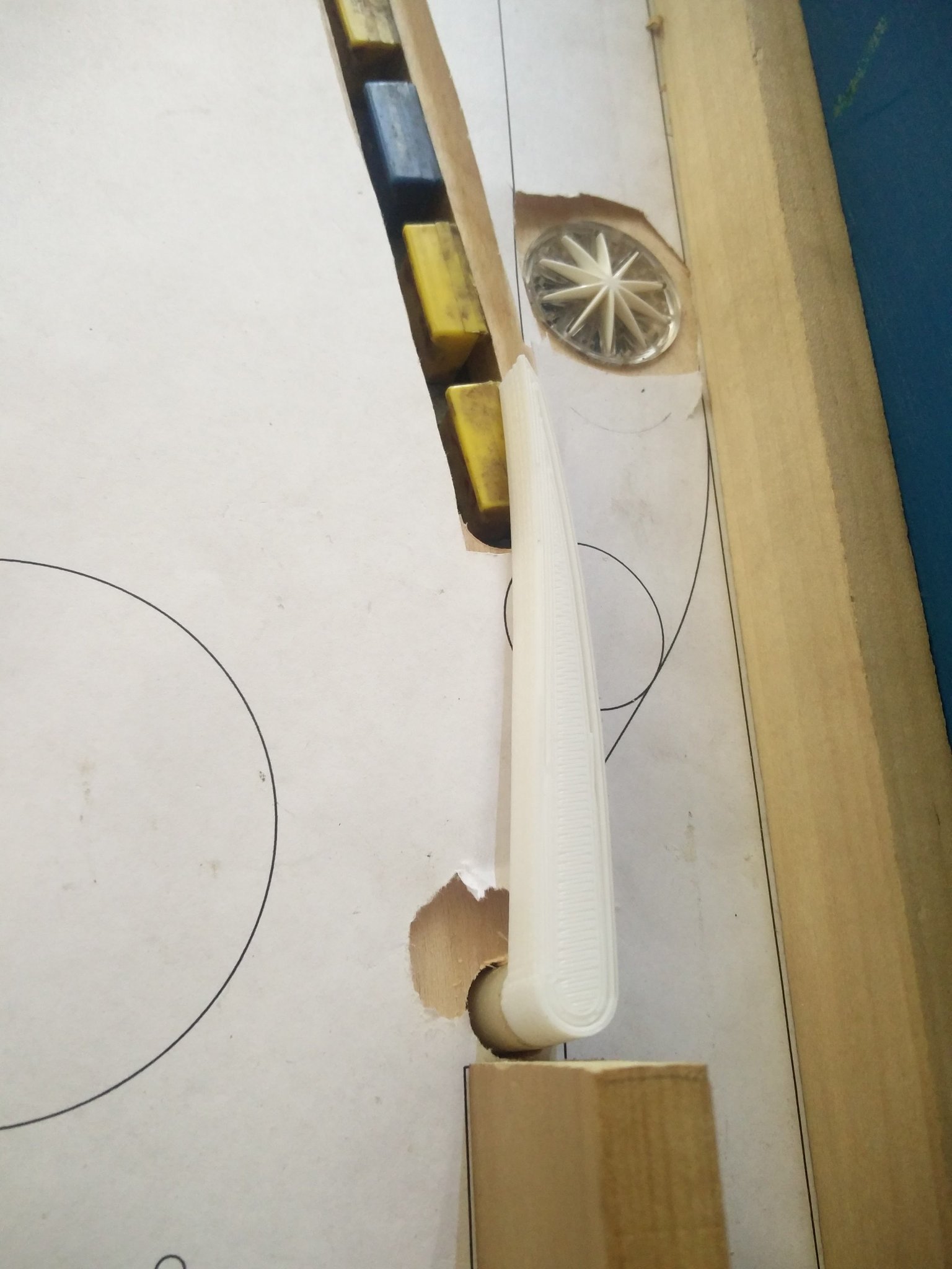
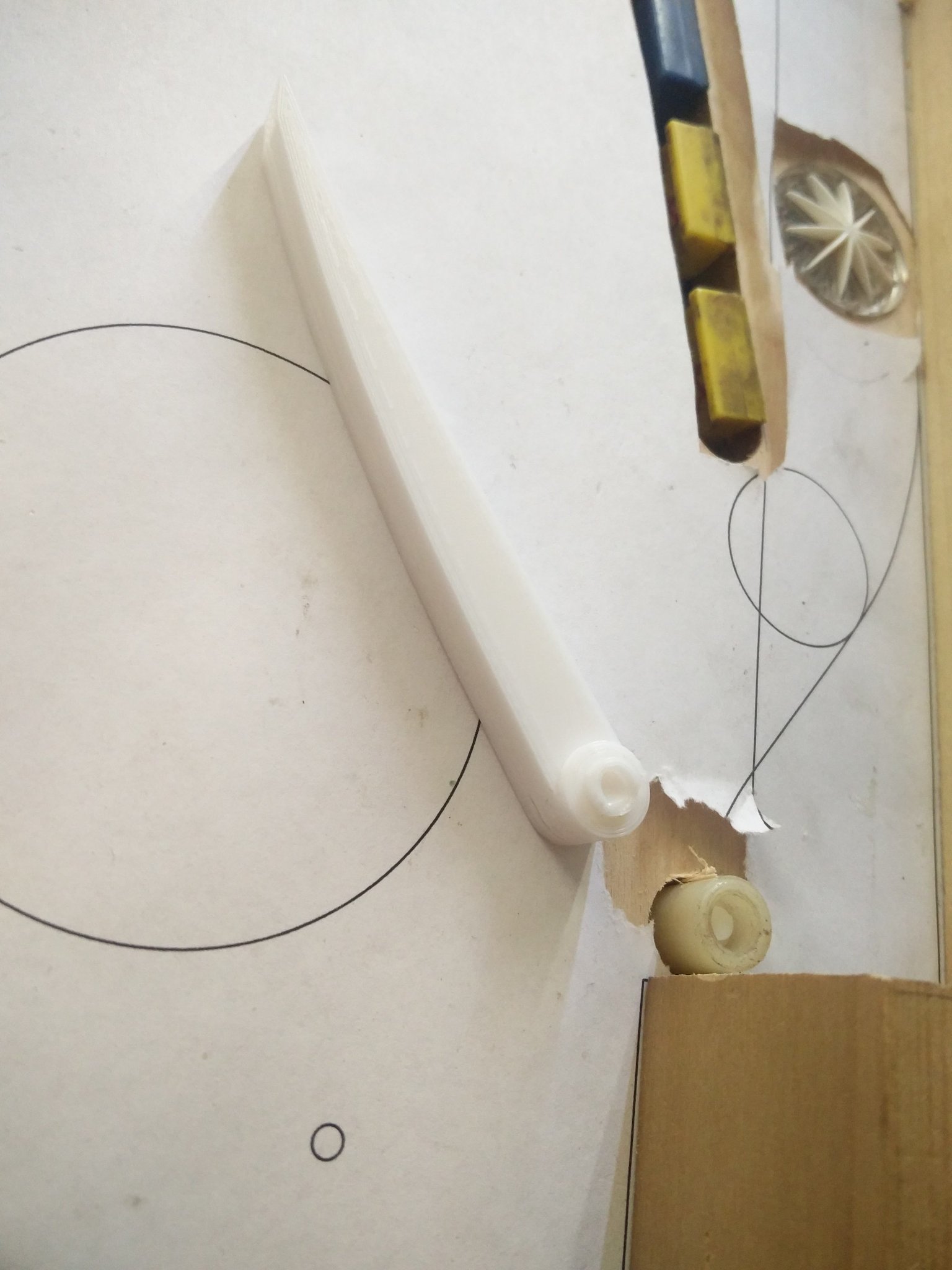
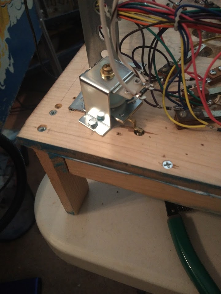
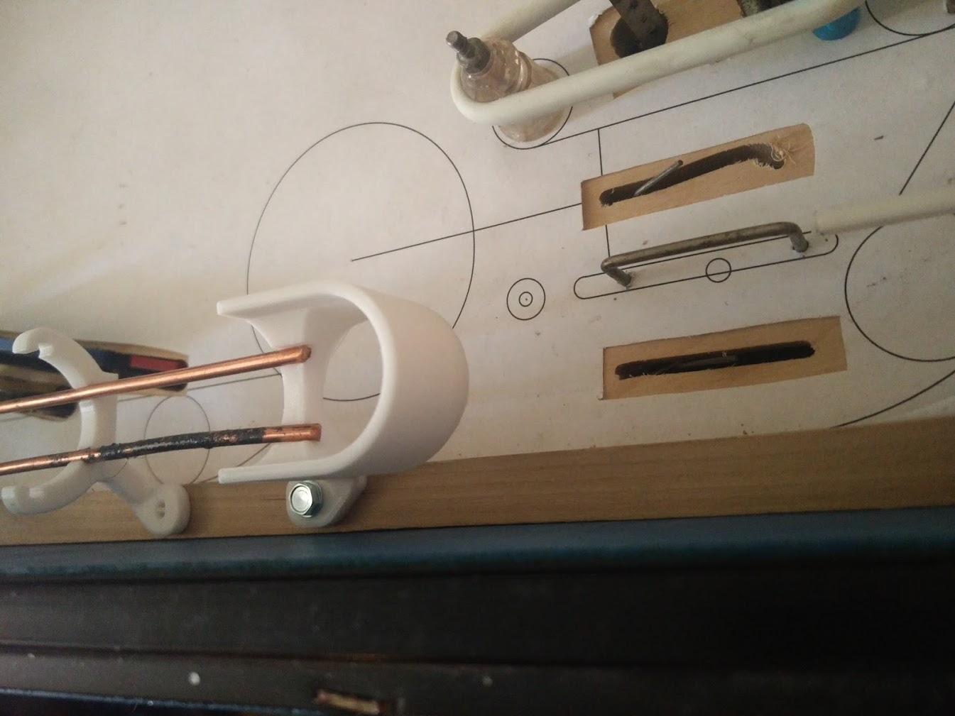
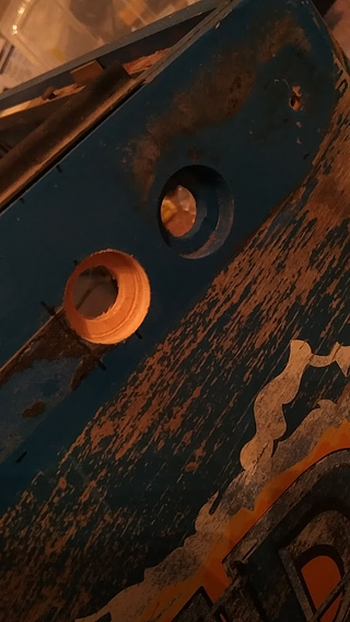
I installed an up-post next to the magnet to catch the ball as it comes around the left orbit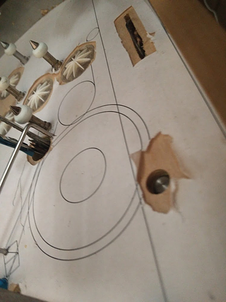

Was a bit nervous about the installation since this wasn't at all planned for, and I had to just eyeball the location, but luckily it did barely fit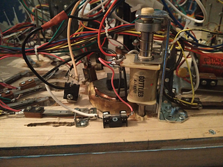
The post itself is a bit smaller than the sleeve, but the sleeve itself is nearly touching the magnet, so I definitely can't really get much closer
Sadly, even with this set up, the magnet still couldn't grab the ball. In retrospect I should have just screwed a regular post in at this location and tested the magnet with that first. If I pushed the ball even 1/4" closer to the magnet, then the magnet had no trouble grabbing the ball, but with the ball leaning against the right wall, there was just slightly too much distance. I can't move the wall, since it's part of the shooter lane, and I can't move the magnet, since it has to be aligned to drop to the upper flipper.
Again, I wondered about having an exposed core, and whether that would be enough, but I didn't want to drill the playfield to find out. Before setting up some test cuts on my spare playfield, I decided to test out the best-case scenario: instead of an exposed core, just expose the whole magnet! I stuck the magnet under the lexan sheet on my test playfield, and ran some wires to test it: 
No problem here. The magnet easily grabs the ball from at least 1-1.5" further than it does with 1/4" of plywood in the way. I'm now very curious how this compares with the large exposed cores Stern uses now, but still don't want to spend $50 to find out. Even that wouldn't be needed though, if I do end up going the route of just covering the entire playfield with a plastic sheet, which is looking more and more enticing as a solution to many of my issues.
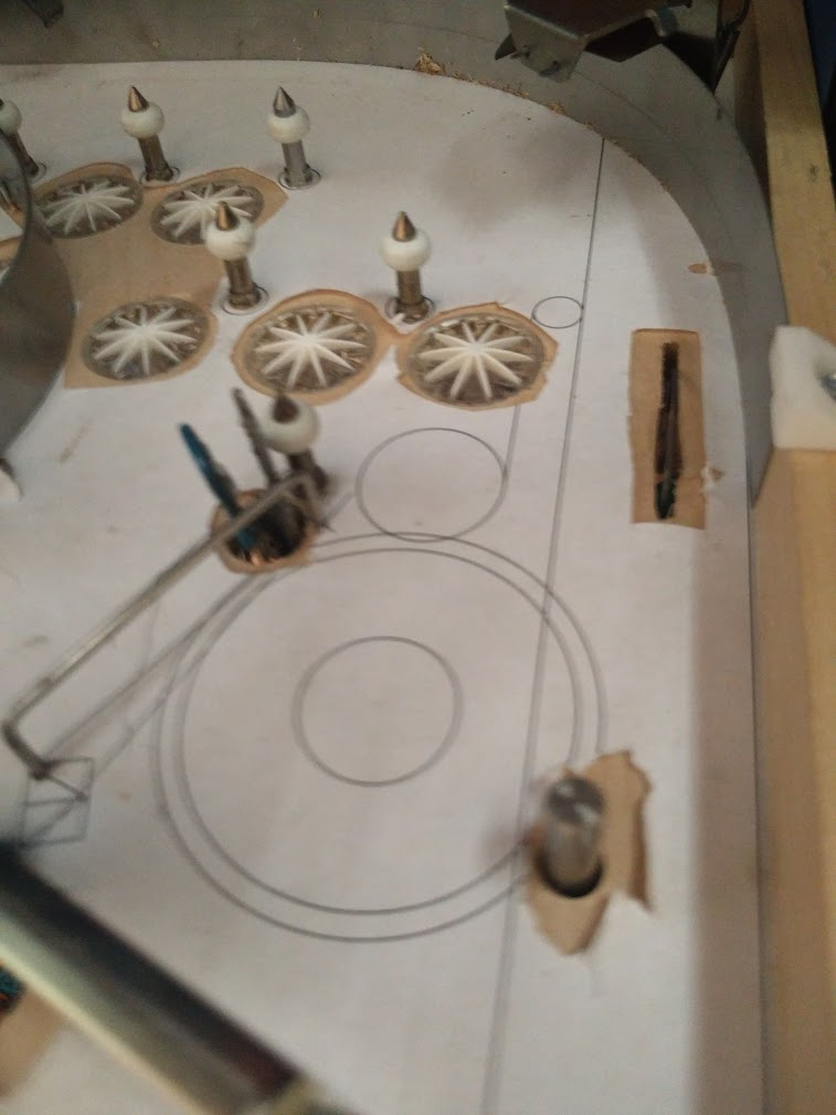
The main problem right now is actually cutting the sheet. Circular holes shouldn't be a big issue, but I'm not sure how cleanly I can make the slots for the target banks. My biggest worry is all the star rollovers. I'd have to cut holes for each of them that align very well with the holes in the playfield, and then raise the rollovers up to be flush with the sheet. I'll need to practice some more with my spare material and see how cleanly and accurately I can make all these cuts. Long term I'd probably need to get this laser cut, but I haven't had any luck finding a place to get a cut this big made yet
Cross posted from the original Pinside thread, this is one of many posts regarding my third homebrew pinball machine, creatively nicknamed 'P3'
Last month I picked up a world cup soccer, and while shopping it I noticed that it had the same style one way gate as one of my spares, with a second wireform to hold the gate open, and that this was the type used by TNA, so it's available from PBL. I did a rough mockup of the part from measuring it on WCS, and it looked like it'd fit, so I ordered the mech from PBL for $30, rather than making another custom mech.

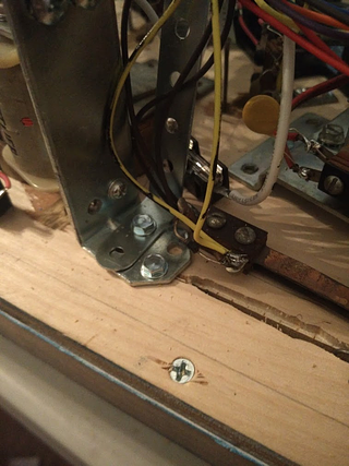
Of course, it didn't quite fit, but I was able to make due. I ended up having to move the mount for my support rails in a bit, and then mounted the gate mech on top of the rail at an angle. I could have put it in a nicer position, but I'd mounted the switches for the lanes in the way. As I probably could have predicted when I decided to do all my switch wiring with one mech still missing, it was a bad idea.
When I hooked it up to test it first, the gate didn't work. I could hear it buzzing, but it wasn't quite strong enough to pull the flap in. If I gave it a small nudge it'd work though. Once I turned the playfield over, gravity did the work for me and it worked fine. In retrospect I realized that this is another mech designed for 50V, not 25V, so I guess I should be happy it works at all. On the plus side that means that it's pulling such minuscule power at 25V that it'll probably never overheat, even without any PWM. I left it on for two minutes and couldn't even feel any warmth from the coil. I like the idea of being able to just have gates and diverters constantly energized, vs having them react when they know a ball is coming at them. There's a lot of times in other games where I get caught by surprise by the orbit coming around or not coming around, etc, since there's no indication on the playfield. At a minimum I think it'd be nice to have a little stop sign insert or something if you're going to do that...
Using a transformer that only outputs 25V seems to be my single biggest mistake so far with the whole project.... It's just continually messing me up since it's not something I ever really thought about before. As much as I like the gottlieb flippers and the general retro feel I think that, if I do another homebrew after this one, I'll either switch to all 50V, or at least get a transformer that can support both, and just use williams mechs...
Cross posted from the original Pinside thread, this is one of many posts regarding my third homebrew pinball machine, creatively nicknamed 'P3'
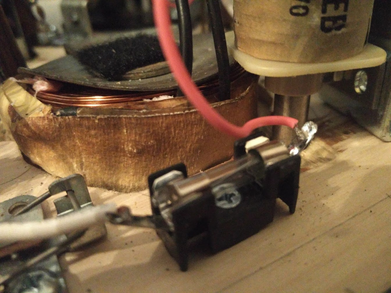
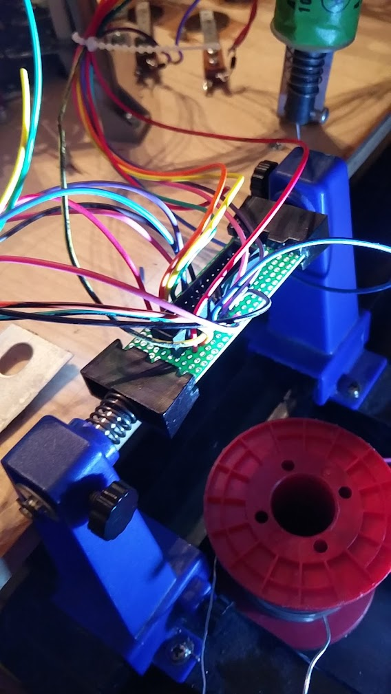
In order to prevent the arcing from destroying my relay contacts, I switched to driving the magnet using a TIP36C that in turn was grounded via the relay instead. That way, the high current is switched by the transistor, so there's no possibility of arcing, while the relay still allows me to control the 50V coil via my 25V driver FET. I mounted the TIP36 on a small bracket made from left over aluminum to act as a heat sink.
With this, the magnet functioned properly, no more locking on, but it also somehow managed to blow my 50V supply's fuse. Even upping it all the way to a 10A slow blow didn't help; I couldn't energize the magnet for more than 1 second. I think this must have something to do with the caps on my voltage doubler, as the lower rated fast blow fuse directly powering the magnet isn't blowing...
Regardless, none of this seems to matter since the magnet still can't grab the ball from the orbit very well. Even with, a medium speed ball thrown by hand, the magnet seems to have almost no effect, let alone being able to grab it. At this point, seeing how bad even 50V is suited for this task, I'm going to stop bothering with this approach for now, and just install a diverter of some kind, as I can't see any of my other ideas improving on it enough for this to be a reliable function in the game. I'm hoping to have at least one multiball be all upper flipper based, inspired by classic lawlor layouts, so having a reliable way to feed the side flipper is a must...
Cross posted from the original Pinside thread, this is one of many posts regarding my third homebrew pinball machine, creatively nicknamed 'P3'
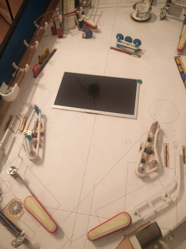
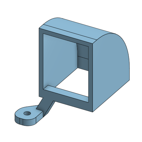
3D printed some brackets for the screen. It's funny, prior to getting a 3D printer "how do I mount a screen under the playfield?" was a really big question mark on my project's todo list. With a 3D printer, I had it mounted just fine with 5 minutes of modeling. 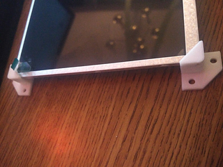
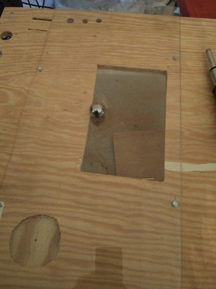
Made a test screen hole in my testing playfield plywood. Messed up the cut spectacularly somehow, my whole rectangle was like 1/4" skewed. Not sure how I managed that when I made it by tracing the screen, but oh well. 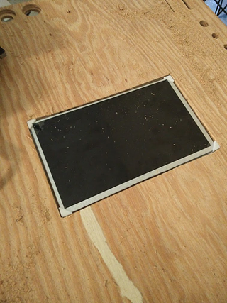
I also tried mounting a test piece of 1/16" lexan over the hole, to see how much it deformed. I screwed it in at the same positions that the nearest posts are on the real playfield, to get an idea of how well it'd be held down. I had problems instantly with a bit of warping, since my holes weren't placed perfectly.
I think that to use this on a real playfield I'd need to pre-drill all the screw holes with a slightly larger bit, so it has some room to slide around while I'm tightening everything down. Then I'd have to work from the center outwards as I attached everything to try to keep it taut. 
My initial test of 'pressing it down with a finger' didn't seem very promising. I could flex the hole down way more than I can on my Black Hole. I still don't understand how the super thin window on black hole is so sturdy when every plastic I've looked at is so much more flexible...
In the end though, I realized I shouldn't be testing with my finger, but with a ball. Setting a ball in the middle of the hole has almost no effect on it, and it seems to roll across it fine. At worse, I can always make a second layer of plastic just for the screen, to bridge that section if it becomes an issue, so this approach still seems viable.
Another benefit I thought of is that I could conceivably mount my magnets way closer to the ball. With wood on top of the magnet, it seems like most playfields are still retaining 1/2-3/4 of their thickness to keep the wood solid, which means the magnet is probably about 3/16" away from the ball in the best case. With a plastic covering, I should be able to cut that down, which should make the magnet stronger, and might help with my issues on the upper magnet. I'm not very familiar with the physics of magnets though... I'm curious how this would compare to the large metal cores on games like TWD. Is a 3/16 thick, 3" wide metal core on top of a magnet generating a larger field than the entire winding itself does?
Next I need to figure out if I can use my star rollovers with it. I used them a lot in the design since they're easy to cut the holes for (compared to a rollover switch slot), but I know I've heard about issues with them and playfield protectors...
Cross posted from the original Pinside thread, this is one of many posts regarding my third homebrew pinball machine, creatively nicknamed 'P3'
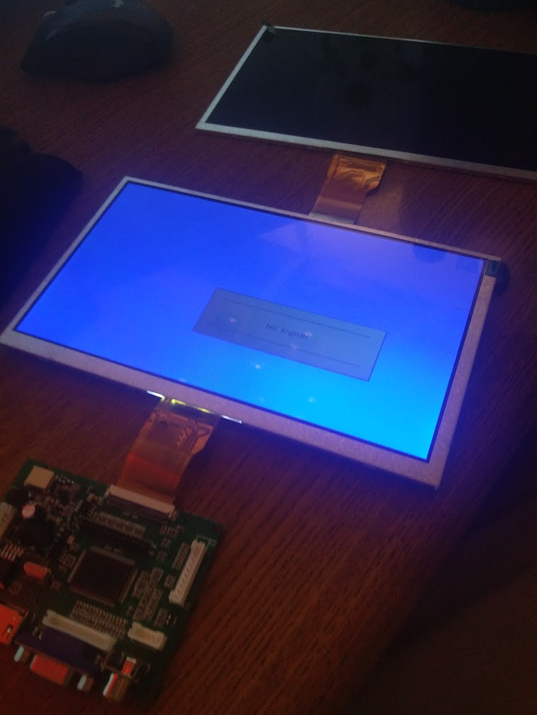
Received my replacement screen today:![]()
Will try to hook it up this weekend and get it displaying some images, then do some text cuts on my spare plywood to figure out mounting, and see how well my lexan sheet will work.
In other fun, my flippers have suddenly gotten very weak (can barely make it up the ramp). I hadn't actually had the game on in the past week or two since I'd just been working on code, so I have no idea how long it's been like this. Always a fun issue even on regular machines, so I'm sure it'll be fantastic trying to track it down here...
I wish there was a reliable way to quantify flipper/coil strength so I could really check on stuff like this, make sure I'm not going crazy, etc...
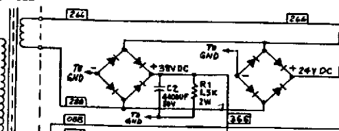
Finally tracked down my weak flipper issue... I replaced the bridge, no change. Replaced the capacitor, no change. Checked signals with a scope, everything looked okay. Cap smoothed the signal out well, peaks were proper height, everything seemed proper. Then I realized... the fuse was blown. I never even considered checking that, since obviously the flippers were working. Something about the way I hooked up two bridges in parallel, one with a smoothing capacitor on it, must have allowed enough voltage to build up through just one side of the AC, through a common ground or something, that allowed it to still get the flippers enough power to flip. Not really sure how that could be, but. I thought I had replicated the circuit gottlieb used on black hole accurately, but the one difference was that I had a separate fuse for each bridge (although I only fused one side of the inputs) while Gottlieb had a shared fuse for both bridges.
I assumed that was just a cost saving measure, but maybe it's actually because of this?![]()
I also realize now, looking at the schematics, that they don't actually fuse the DC side of the bridge, which is interesting. I guess they figure that the per-coil fuses will usually catch those issues? I guess they usually do, at least in my experience. I definitely didn't fuse my solenoids enough overall. I put separate fuses for each flipper and bumper, but the controlled coils only have the one shared fuse on their driver board. More concerningly, I've never blown the on-board fuses for some reason, but I have blown the rectifier fuse when a coil locked on, despite the rectifier fuse being 8A slow blow and the on-board being a 4A fast blow. Hopefully that doesn't become an issue.
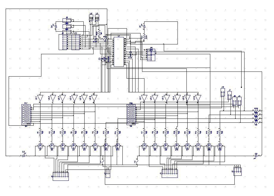
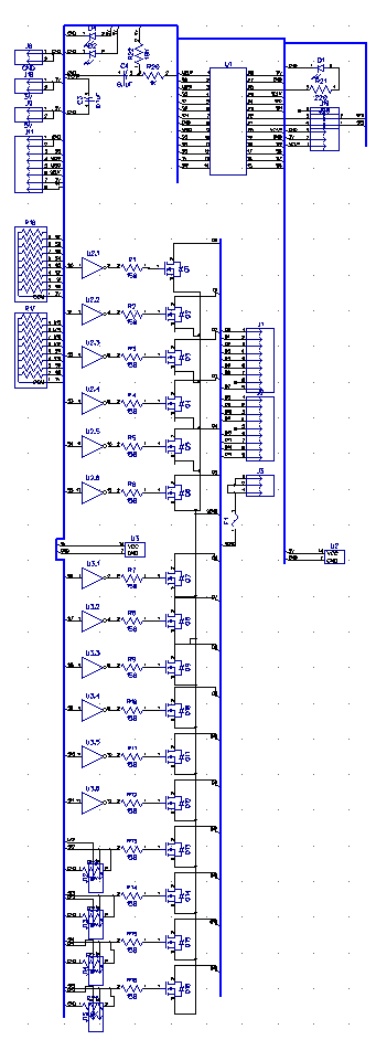
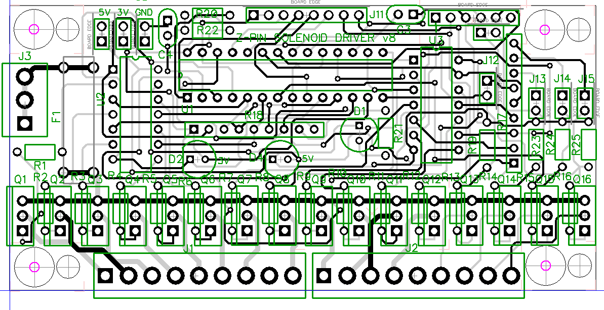
I've also designed another iteration of my driver board since my rev 7 that I assembled still had mistakes, though I haven't ordered it yet since I'd like to get some more boards done for a combined shipment. This time, I restarted from scratch. My previous schematic had been carried over and repeatedly modified since my original rev 1 board back when I started learning how to design boards, and was a bit of a mess.
Before: ![]()
After:![]()
I'd also been repeatedly running into issues when designing the boards trying to fit them in a 2x4" footprint. Over time I went from 13 FETs to 16, added driver chips, fuses, test points, indicator LEDs, etc while still using the same size board, and it had gotten really hard to layout. This time I scrapped the voltage indicator LEDs, and dropped from two fuses (one for each bank of 8 drivers) to one fuse. Originally, I had designed the board so each bank could be operated completely separately, and could be configured with pullups for PNP transistors or pulldowns for NPN transistors, so that it could also be used to drive an 8x8 lamp matrix, but that use has sorta disappeared in the intervening years.
Those part removals combined with some tricky layouts let me finally get all the transistors layed out neatly. This also means that I can now stick both solenoid connectors on one side, and keep all the low voltage signals on the other side of the board, to clean up the wiring a bit more
Rev 7: ![]()
Rev 8: ![]()
Yesterday my second screen shipped out, so of course today my original screen I ordered from China arrived out of the blue.. Only took 2 and a half months. This one included a USB power cable, which is nice since now I won't accidentally fry anything by using -12V, but it's also weird, since USB is 5V. As far as I can tell, the boards are identical. Not sure if there's something I can't see that's different or if one of the sellers was wrong about the supply. Was also able to confirm that my first screen is still good, so I must have only damaged the driver board, so now I've got a backup. And soon I'll have two boards and 3 screens. My attempt to get a cheaper screen from china has now cost me about $130 ![]() I guess that's what I get from ordering something from overseas during a pandemic though
I guess that's what I get from ordering something from overseas during a pandemic though
![]()
Cross posted from the original Pinside thread, this is one of many posts regarding my third homebrew pinball machine, creatively nicknamed 'P3'
My screen still hasn't arrived, so I gave up and ordered another one. Hopefully it will arrive eventually..
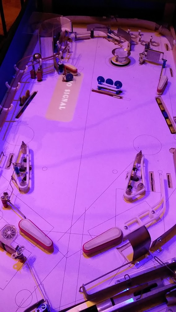
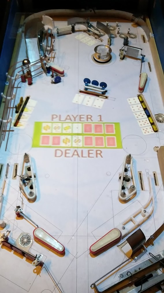
In the mean time, I tried out an idea I'd been toying with for a while. I don't know where any of my lights will go, or how the art will look, and it's hard to play with that, so why not make some temporary artwork?
![]()
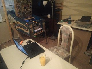
I dug out an old projector, and hung it from a 2x4 sticking out from my upstairs landing, and lined up the game underneath, then I loaded up a quick mockup:
![]()
I expected it to be a bit hard to play like this but it was actually surprisingly easy to ignore and play like normal. The quality isn't very good though; the cards aren't readable even at 1080p. With a 4k projector this might be workable beyond rough prototyping, but it'll probably work for now. I also had to put the projector really high up, probably 10+ft off the ground. Gets to be a real pain turning it off and on without a remote ![]()
With this I'm hoping I can get the game much more fleshed out before needing to commit to making a new playfield and moving everything over
Cross posted from the original Pinside thread, this is one of many posts regarding my third homebrew pinball machine, creatively nicknamed 'P3'
Coded the logic for actually determining which hand won, and displaying the best 'hand' from each hand of 7 cards. The code for finding pairs, straights, etc was surprisingly simple and fun to write.
Since it can identify what hands you got, I can now tie that into what modes/multiballs are enabled at that point. Unsure what I should do if you manage to get multiple different hands.
For instance, what if you manage to get three pairs? Technically only your better two pairs will count as far as the poker game goes, but if each pair qualifies a mode, should you have the choice of which one(s) to play? Should only the higher two pairs' modes be lit, effectively making lower cards' modes harder to get?
If you get a straight and a pair, and then you play the mode you get from the pair, does the multiball you got from the straight go away, or could you go play it after finishing the mode?
If you qualify a mode, but then immediately go into the shooter lane to start another round of poker, should you lose that mode, or should it still be available? Should you be able to start a mode mid-way through a hand?
So many questions... Luckily the decisions on these aren't really hard to change the code for, they could even be settings technically, although I'm not going to bother coding any settings menu or anything since I can just edit the code ![]() I'll probably go with the most restrictive options for now (if you take a mode you lose your multiball, etc) just so I don't have to deal with coding a mode select screen yet.
I'll probably go with the most restrictive options for now (if you take a mode you lose your multiball, etc) just so I don't have to deal with coding a mode select screen yet.
Cross posted from the original Pinside thread, this is one of many posts regarding my third homebrew pinball machine, creatively nicknamed 'P3'
Coded some initial spinner rules. First time you shoot the spinner, it stops it in the upper lanes. Next time it orbits around back to the left flipper for a 2x spinner shot, and stops it in the lanes. Then you get two orbits before it stops it, etc.
Coding this was way harder than that sounds, due to me not really thinking about 'shots' and such when I designed the playfield. A ball shot through the spinner could go in one of six lanes. Or it could fall back through the spinner. Or fall down the shooter lane. Or it could manage, theoretically, to go below the left one way gate and continue on to the left. When the gate is open, it will usually go all the way around, triggering the left orbit switch and the left inlane on its way down. But it could also fall short into the upper eject, or go under the ramp, or fall even shorter into any of the lanes, etc from before.
Originally I figured I didn't need to care about this too much. I'd just consider a shot to the spinner as whenever the spinner suddenly spun a few times. But when I'm purposely designing the code to let you repeatedly rip the spinner, it's very likely the spinner will still be spinning somewhat by the time you rip it again, or you could even go right under it while it's spinning, so I ended up with a ton of code for different edge cases trying to detect when the player does a successful orbit or not, multiple timers going on, etc. It's a bit of a mess, and it's going to be even more of a pain to debug if something goes wrong.
It would have been really nice to close up some of the areas a bit more so I could know 'for sure' whether a ball passed through there, rather than having a big open area up there for the ball to bounce around in. Too bad big areas for the ball to bounce around in are fun...
Scoring wise, I'm trying to sorta take a page from Meteor, since I like the way its spinner value is continually fluctuating. For the first iteration of that, my attempt is to make the spinner score more when you having matching numbers of drop targets down on each bank. For instance, the spinner starts at 10 points. You knock down one target on bank A, that goes up a bit. You knock down one target on bank B as well, that number goes up even more. Two targets down on each bank is better than one, etc. I'll try to balance it so you can get the spinner up really high, but at the same time if you hit one stray target it may ruin it completely.
Hopefully this will also encourage people to 'shoot around' more, instead of finding one or two banks they feel safer on and just picking targets off those
Cross posted from the original Pinside thread, this is one of many posts regarding my third homebrew pinball machine, creatively nicknamed 'P3'
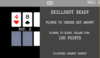
Coded the basic structure of the skillshot. I'm pretty dissatisfied with most skillshots in games currently. Most seem to either be 'just plunge the lit lane', or plunge to a flipper and hit a lit shot. You don't really care about your plunge at all. Some games like Deadpool make it a bit more interesting by locking in your lane choice. Most games that actually require you to plunge to a specific spot (such as Taxi) just make you learn one or two plunger positions, which I think can get boring once you've learned them, since at that point you're just slowing down your game to squint at the plunger. My goal here is to have a lot of different places to plunge to, and have the context of the game make you change which one you're plunging to frequently.
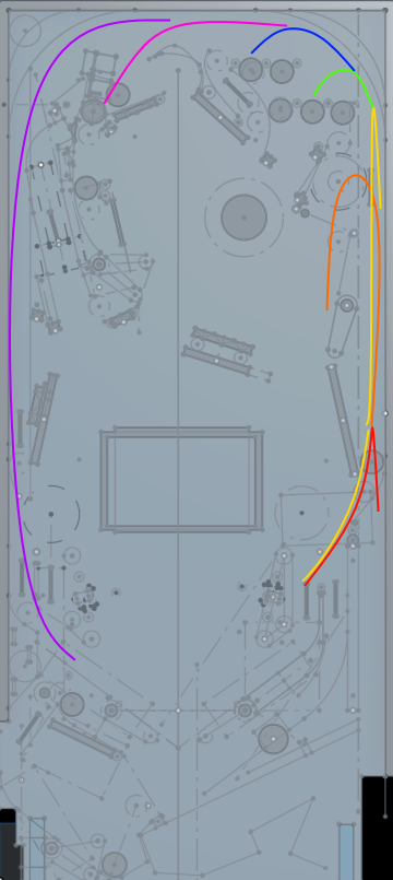
There are seven different places to plunge to:
Red: plunge just far enough to clear the diverter. Diverter will close, leading ball to right inlane
Orange: plunge so that the ball hits the lower magnet switch, without hitting upper magnet switch. Magnet activates, pulling ball to the left and feeding upper right flipper (well, hopefully, if I ever get it working)
Yellow: if you plunge past the magnet and hit the upper magnet switch, you'll fall back down and feed the right inlane, similar to the red skillshot
Green: The lower 3 lanes. Not sure what will happen with each lane yet, maybe one will be lit as an extra target
Blue: Upper 3 lanes, same as green
Pink: plunge and fall into the upper eject which will then feed the upper left flipper. Really hard to do, worth the most
Purple: Hard plunge all the way around and feed the left inlane
The Pink and Purple skillshots are made harder since there's a one way gate to the left of the lanes, blocking them. Currently I have it timed so it's open for 2 seconds, then closed for 2, so you'll get redirected to the lanes or let through based on your timing.
Your current 'bet' amount is determined by where you plunge, so you can choose to bet a little or a lot while still keeping it 'pinball'. I'm thinking the bet amounts will be percentages of your total 'bank', so you'll be forced to bet more later in the game. You can return to the shooter lane at any point while playing your poker hand by shooting under the upper right flipper, so you can adjust your bet if your hand is looking better or worse.
In addition, there will be an award on each skillshot, that you can only get if you 'call' your shot by selecting that award with the flipper buttons. Currently it's just points, but I want to eventually put other stuff in there to mix stuff up. If it's only ever points, they'll either just be ignored, or they'll be so big they're unbalanced, so I like to put 'in game' effects into stuff wherever possible. But that will have to wait until I have more game coded to affect.
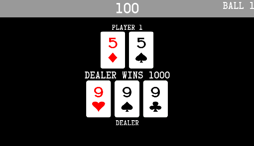
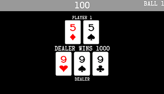
The graphics themselves on the screen are pretty basic right now, but serviceable. I kinda dread getting to the point where I actually need to make this stuff look nice somehow. Even for a simple screen like this, I think more code is dedicated to drawing and updating the screen than there is to the actual skillshot logic... It must have been nice in the DMD or alphanumeric games where you could often just slap some text up and be done with it
Cross posted from the original Pinside thread, this is one of many posts regarding my third homebrew pinball machine, creatively nicknamed 'P3'
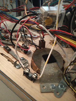
I've spent a good amount of time playing with the upper magnet. It's positioned next to the shooter lane, right orbit, so that it can drop the ball to the upper right flipper.
The magnet had two use cases:
1. for the skillshot, if you plunge the ball up so that it stops next to the magnet, and then the magnet activates, pulling the ball sideways from the shooter lane to then release it to the flipper
2. to feed the upper flipper via left orbit shots. this is the main use case, with the skillshot just being a bonus. I didn't really forsee a problem with this while designing, but I've come to realize that this just isn't how magnets are normally used in machines. Games like Twilight Zone will stop a fast moving ball on an orbit, but they have the magnet directly under the ball's path. The magnet acts only as a ball grabber, not a diverter. Most cases I can find of magnets being used as diverters are things like TWD's crossbow, or WCS's lock. WCS is the closest to my use case, since it specifically grabs a moving ball, stops it, then drops it. But even WCS has issues grabbing a fast moving ball.
I quickly discovered that my original plan of wiring and mounting this magnet the same way the magna save is mounted just won't work. The magna save coil is being powered using 25V, while most newer games use 50V for their magnet. So I hooked up my 50V line to my magnet relay, instead of 25V, and... immediately fried my relay. The 50V is strong enough that, when the relay deactivates and its contacts move apart, the voltage will just arc across the gap and continue powering the magnet while melting the contacts. I had a similar issue with the 5-bank reset coil, and was able to fix it by adding a 10uF, 300V capacitor across the contacts. For some reason this doesn't work on the magnet. I wondered if the magnet was stronger, but the magnet actually has more resistance than the drop target coil. My random relay was only rated for 3A@25V though, so I ordered a really beefy relay, which was rated for 30A (!). I think my magnet should be drawing about 10-12A at 50V, so that should be plenty. But that relay also had constant arcing issues. I tried bigger snubber capacitors, other snubbing solutions, even disassembling the relay and physically bending it so the contacts are farther apart, and nothing helped.
It seems like switching 50V@10A just isn't reliable via a relay somehow, though I don't understand why. Modern games all control their magnets via transistors and mosfets, although I don't know if that is specifically to avoid this issue, or for other reasons. The problem is, I can't use those here, since my 50V has a separate ground from my 25V. My next plan is to get a TIP36C (which is what williams used for their 50V coils in the 90s), and then try to use a relay to switch the gate (instead of having a microcontroller switch it like normal) which feels like horrible overkill, but it may work. Even at that point, I'll still have issues because I can't PWM a relay, so I'll basically be running the magnet at full power. I'm not sure how long I can power the magnet like that, hopefully it's long enough to get the ball settled.
The magna save is also a completely 'below playfield' magnet, with no visible core. Adding a core that goes all the way through the playfield helps make the magnet stronger, and I assume that this is why games like TWD, which need to grab a ball shot at their wide bash toys, use an even bigger exposed magnet core. At first I figured I should just order one of those larger exposed cores, but they're incredibly expensive somehow (the large core costs more than the magnet itself!). Even a regular size core is expensive. I don't really want to spend that much money on something that may not even be useful, so for now I've just bought some 3/4" steel roundstock that I'll use to test the smaller exposed core. I can't find any info on how much stronger this make the magnet.
All this is still up in the air, too, as I don't know if the magnet will be able to grab the ball properly even with a large core and 50V, given the crazy speed my left orbit shot has. I've spent a lot of time trying just to get the 50V to work, and still haven't been able to even do a single test yet to see if the 50V can grab the ball since it keeps melting stuff ![]()
I'm also trying to consider other approaches, such as replacing the magnet with a physical diverter, but currently I can't find any good way to fit one in with my current constraints, and I would still need a magnet or an up post to hold the ball for a reliable side flipper shot after the diverter gets the ball to the flipper...
I may also try putting an up post in the shooter lane, specifically to stop the ball as it comes down the lane from the left orbit, and then using the magnet to pull the stopped ball over the flipper. I am running low on drivers for the coils though, so I want to avoid adding in more coils if possible...
Cross posted from the original Pinside thread, this is one of many posts regarding my third homebrew pinball machine, creatively nicknamed 'P3'
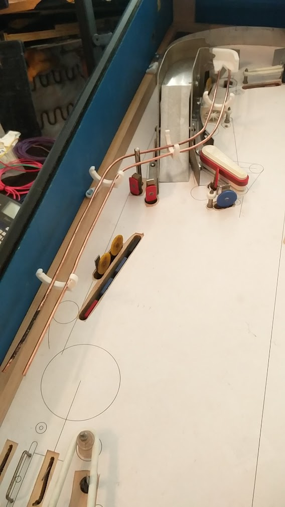
Got the basic habitrail installed. Made a half height, low quality mount to hold the other end, which seems to work okay. 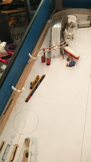

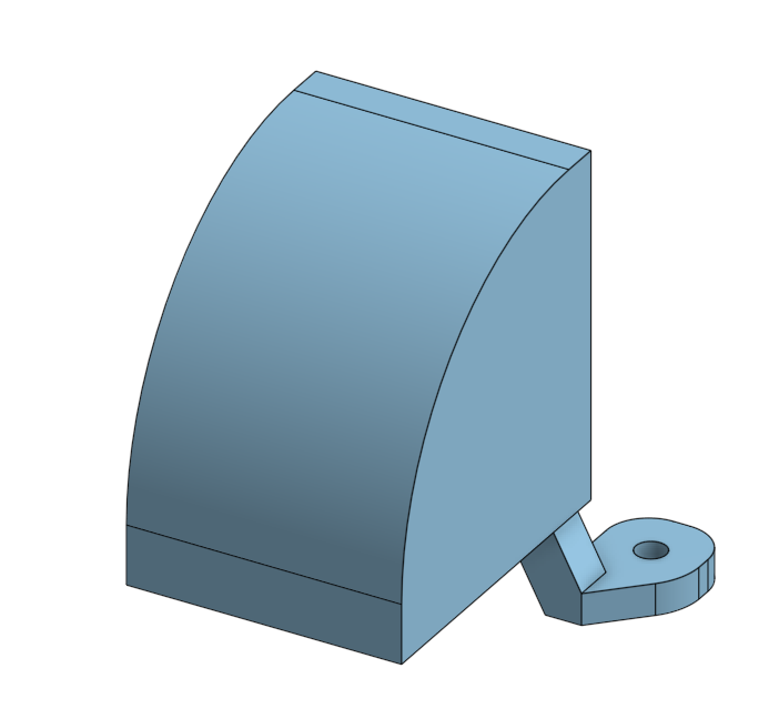
It looks like I can make the curve on the entry mount wider for a smoother feed. This is the original: 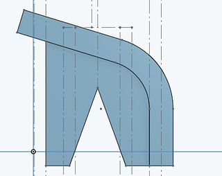
And here's my current iteration: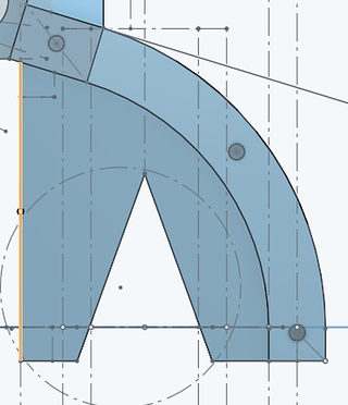
Mounting the entry mount was also an issue, since I didn't really plan for that. I ended up putting it on a standoff on top of one of the existing ramp's mounting holes, but I still only have one screw holding it. It seems to work okay, so I'll leave it for now. I could probably extend another support out to the posts behind the 2-bank if necessary, but I don't want to cover the playfield any more than necessary.
I also needed a place to mount the switch, so I stuck a microswitch through a small gap. To prevent airballs, I put holes on the top to screw a sheet of clear plastic into. Still need to figure out how to attach the plastic on the left side of the ramp. I don't understand how Mars never has airball issues on its ramp... seems hard to believe that they managed to make it the exact height needed for their flipper strength, especially since I'm using the same flippers!
This is my final entry design. Looks pretty weird, but it works. :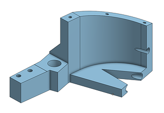
I had to add some side rails to keep the ball from falling off, especially at higher speeds. Lock post worked on my first try with a random guess for the pulse length, which surprised me. 
While it's nice to know this works, I probably will avoid locking multiple balls this way, since I don't have any way to mount a switch behind it to know if it failed to release a ball due to the ramp positioning. Sadly, this was the only position I could fit the post mech in, so I'm a bit constrained here. I'mthinking I'm going to have most multiballs work by locking one ball on the ramp, and then you get a second ball to plunge, and the ramp ball is released once you hit a switch. Maybe there will also be something to let you short plunge and combo up the ramp to lock a second ball, for three ball, or a rule about locking both balls during MB to release a third. Since there's no auto plunger I can't really have a normal add a ball. I feel like multiballs lately have been a bit boring design wise, so I'm hoping to do more stuff with multiple phases like DE used to do, or maybe more advanced stuff like a special multiball that you can only work towards qualifying while you're already in another multiball, at the cost of ignoring the current multiball's jackpots to make that progress...
For normal ramp shots, I programmed the game to engage the post as soon as the ball makes the ramp, and then disengage once the inlane switch registers, but I had issues with the ball bouncing over the switch since it was just dropping off the end.Inspired by Metroid which I saw at Pintastic last year, I made this end cap for the rail to make the ball drop nicely. 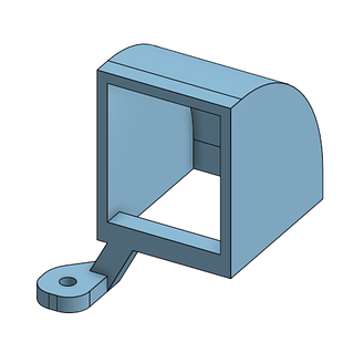

It worked, but I didn't like how it looked, so I made this instead, which seems to work fine and looks more natural:

Cross posted from the original Pinside thread, this is one of many posts regarding my third homebrew pinball machine, creatively nicknamed 'P3'
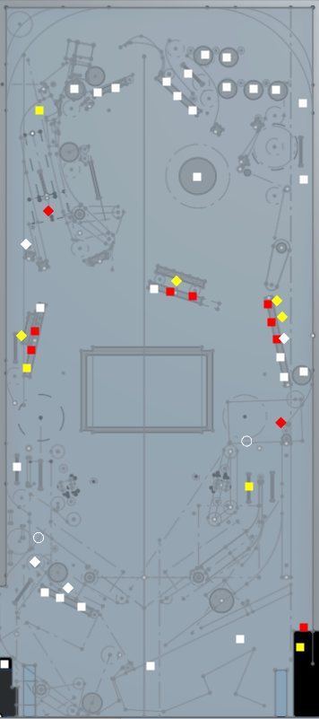
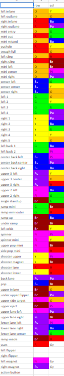
Here's a big case of 'wish I was using MPF'... Testing live on the machine was a pain since it was at the other end of the house from my regular computer. So I wanted to be able to easily test stuff virtually. MPF has a nice application for this. Lets you import a picture of your playfield, then drag and drop switches, lights onto it. Pretty handy, so I recreated it using my new rendering capabilities. Not a ton of work in the end, although mine lacks some polish...
Squares are switches. Red means closed, yellow/white means open. Left click to toggle open/shut, right click to quickly press the switch and release it again. Diamonds are coils, they turn red when energized. The white circle above the right inlane is a light, currently off, currently wired up as a 'lower ramp w/lit'.
Another in the left outlane will turn green when the mini-playfield is enabled, triggering the down post to let the ball in. Hopefully I can use this to get a slightly better feel for where lights will go.
I also added some code to do stuff like automatically opening the drop target switches when the bank resets, auto closing the shooter lane switch after a ball is released from the trough, etc. Stuff that would happen physically on a real machine. Otherwise it gets to be a pain to use, since the drop target coils would repeatedly fire until you remembered to click each switch again
Cross posted from the original Pinside thread, this is one of many posts regarding my third homebrew pinball machine, creatively nicknamed 'P3'
Code can't get very far without some read-outs. I don't have any lights yet, so for now my 'screen' will have to do. Currently that 'screen' is a 50' HDMI cable running to my livingroom TV, but it'll do.... I spent a long time trying to find a good R-Pi compatible graphics library that would work with Typescript/Node. For some reason, everything seems to have been abandoned 2-3 years ago, and doesn't work with modern Pi operating systems. I'd be fine with even coding the graphics from scratch with a plain OpenGL context, but even a simple library to provide that seemed to be missing.
Eventually, I found a simple library that supported things like basic shapes, images, and text, that was designed specifically for RPi game dev, but had been abandoned partway through development. The author's last update said that they were working on keyboard/mouse support, since without that a game graphics library isn't very useful. Well, it's useful to me! no keyboards here...
Only problem was, it didn't work with the latest RPi OS, since they introduced a new graphics card driver, and it wasn't compatible with Windows (my dev OS). So I dug in, forked it, and made my own version with RPi 3 support, some features and bug fixes, and, with one late night hacking session, a shaky but usable windows port. Not too bad, all things considered. The nice thing about this, vs using an established library (if one had existed), is that if I find any other bugs or shortcomings, I can just easily add whatever I need, since I'm already maintaining my own fork.
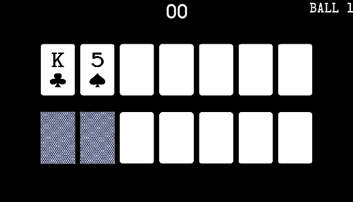
With that out of the way, I got some initial status displays set up. Very rough currently; I am not in any way an artist. Hopefully I can work up something half decent for the screen at least, but actually doing some art for the playfield is probably beyond me... More mountains to climb down the road ![]()

I can add more cards from the drop targets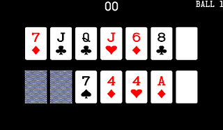
No scoring or ball logic hooked up yet though... I also need to figure out what exactly is actually going to happen once you complete a hand. To keep with the 'real poker' goal, technically you should have a final opportunity to bet before your opponent reveals their cards, so I figure you'll need to shoot a shot that can hold the ball to finally flip the cards and declare a winner. In this case, my only ball holds are the upper eject hole, the ramp, and the shooter lane, so I'll have to figure out some logic for that, as well as how exactly you can 'fold' if your hand is looking bad. I'd like it to be something on the playfield, vs some menu interaction, but it has to be something very hard to hit accidentally....
Current lines of code: 4,106
Cross posted from the original Pinside thread, this is one of many posts regarding my third homebrew pinball machine, creatively nicknamed 'P3'
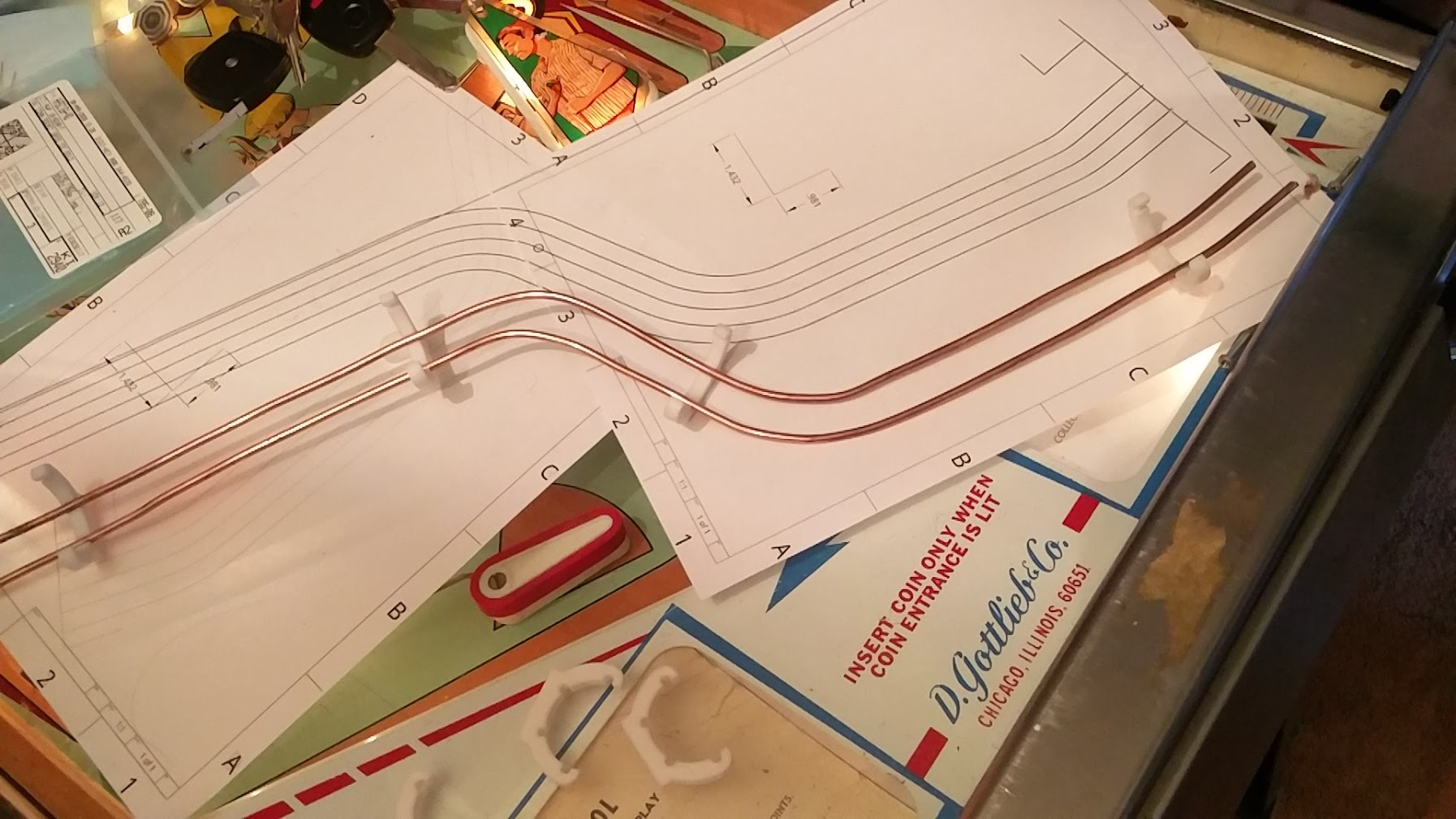
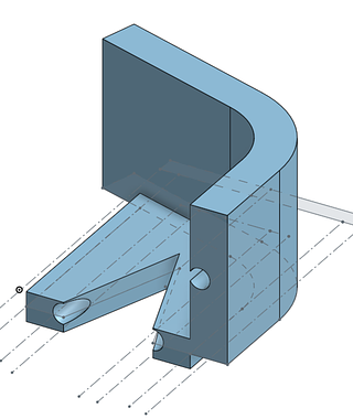
Began work on the habitrail for the ramp, to return the ball to the left inlane. I 3D printed some clips with flat bottoms to make it easy to hold the rails while I align them and work. The plan is eventually to either use some brass and solder it, or try to braze some steel, but for now, I'm using some easy to bend 1/8" copper wire (and cheap, since it's just on spools at Home Depot) to get it right and test things. I'm curious to see if the clips can hold up to soldering/welding, it'd be convenient. 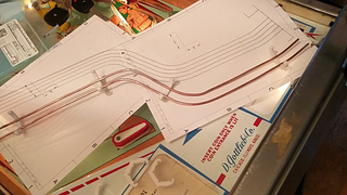
The actual alignment is a bit iffy; since my ramp model didn't match the actual model that means the habitrail I drew won't line up with the physical ramp either. I tried to eye-ball adjust it to match where it looks like the ramp actually is, but we'll see how well that works.
The actual attachment to the ramp will also be weird. It was designed to connect to a plastic tube that goes across the playfield, and didn't have much flow. Originally I just sorta hand-waved this part as "I'll make something to hold the habitrail, can't be that bad", but now I'm at the part where I need to actually figure out how to connect a ramp whose shape I don't know to the habitrail I haven't built yet.... Here's my first attempt. I'll probably just have to print this a lot of times to get the fit right, assuming the basic shape even works.
Cross posted from the original Pinside thread, this is one of many posts regarding my third homebrew pinball machine, creatively nicknamed 'P3'
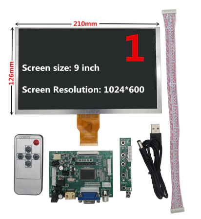
Earlier, I went searching for an LCD to put in the middle of the playfield. After a lot of digging, I ordered this 9" screen from AliExpress. Seems to have HDMI support and can be powered with my ATX power supply, but it's hard to tell for sure. There's a ton of different badly documented screens for sale, with conflicting information about what they support or how to drive them. It seems like there's really only two driver boards floating around, one with VGA support and one without, judging by the pictures, but some of the items for sale are clearly wrong about what they're offering. Lots of fun. But for ~$30, I'll take some gambles. Any screens for sale from more reputable US sources seem to be $100+ which is a bit ridiculous. Originally I planned to just buy a monitor and strip off the case, but it's hard to even find a 9" monitor, and the more common 10" won't fit my playfield.
Sadly it's been more than a month since I ordered the screen, and it still hasn't arrived. Tracking last showed it leaving China on 3/30, so not sure if it's gotten lost or just stuck in customs or something forever...
Not a super big deal, I guess, since I don't have any way to really mount it yet.
I'm investigating different options for plastic to cover the hole. Not sure what material is best as far as being pretty sturdy but also thin and scratch resistant. Based on the Voyager homebrew, I'm also wondering about just using a single large sheet of plastic for the playfield as opposed to recessing a smaller cover. I wouldn't have to worry about routing out the recess for the window, or about doing any inserts either, and no need to clearcoat. A lot of other possible issues arise though, so that'll need some more investigation. Once I can find better what material to use, I'll try to order some sheets for experimenting

Cross posted from the original Pinside thread, this is one of many posts regarding my third homebrew pinball machine, creatively nicknamed 'P3'
While getting some basic code running to reset the drop targets and eject the holes, I suddenly lost an entire bank of solenoids. Inspecting the board, I eventually figured out that the board had been repaired so many times as I modded it to test different things that one of the traces carrying the solenoid ground had just gotten ripped off completely. At this point it probably had 4 jumpers on it already, and multiple cut traces, plus some of the mosfets had been replaced three times, so I decided it was time to junk that pcb and build a new one.
One of the main issues that required all those modifications early on was my changing requirements for how the inputs would work. First I'd had them active high, then active low, and then I'd had to change which pin they were. Back when that happened, I redesigned the board to add some more configuration points, so each I/O could have a configurable pull up/down, as well as fix some other pain points. I added LED indicators that the fuses were good, test points for the voltages, and combined my 6/6/4 pin connectors into two 8 pin connectors. A big goal on these boards as I design them further is just making the connector count as small as possible, since they needed to get unplugged so often. I'd actually had the new PCBs on hand for months, but hadn't needed to actually use one yet, so I started assembling: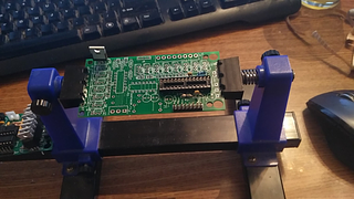
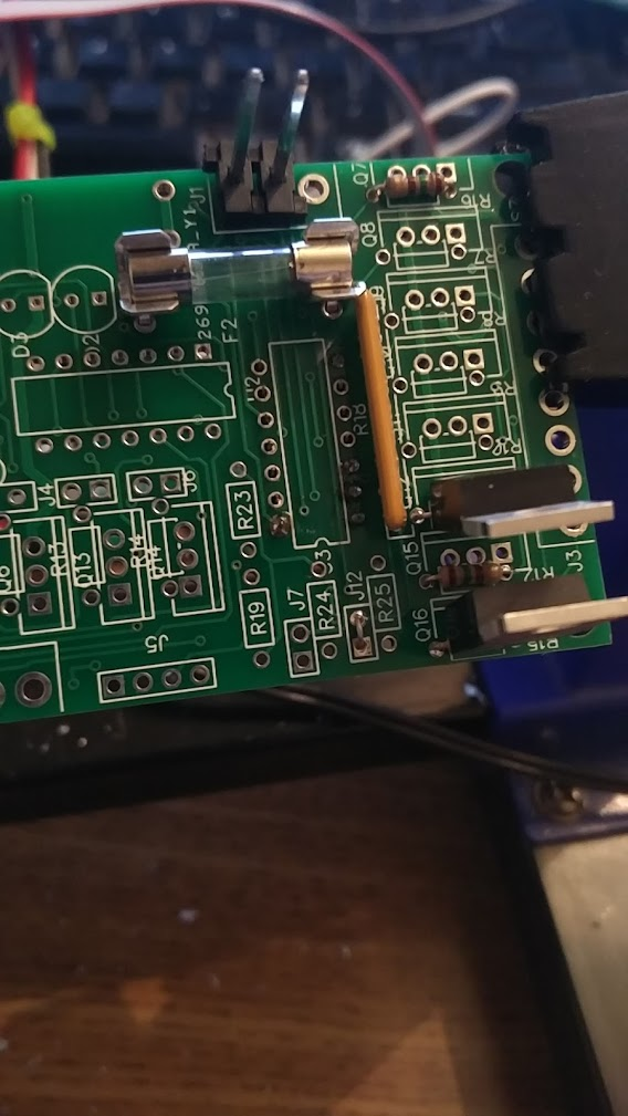
Sadly, I discovered an issue with my design early on: at some point I had mirrored some of the components. For the mosfets, that wasn't too bad; just turn them around, but I'd also mirrored one of my 16 pin chips, which resulted in the horrible hack of mounting the chip upside down:
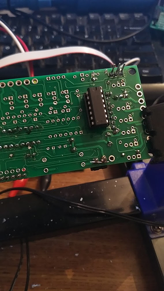
Sigh. I guess another pass at the design will be needed down the line. It'll work for now though, just hard to mount 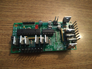
Cross posted from the original Pinside thread, this is one of many posts regarding my third homebrew pinball machine, creatively nicknamed 'P3'
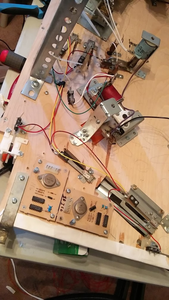
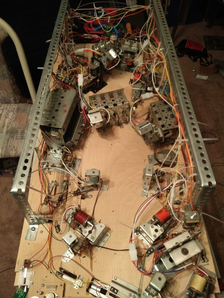
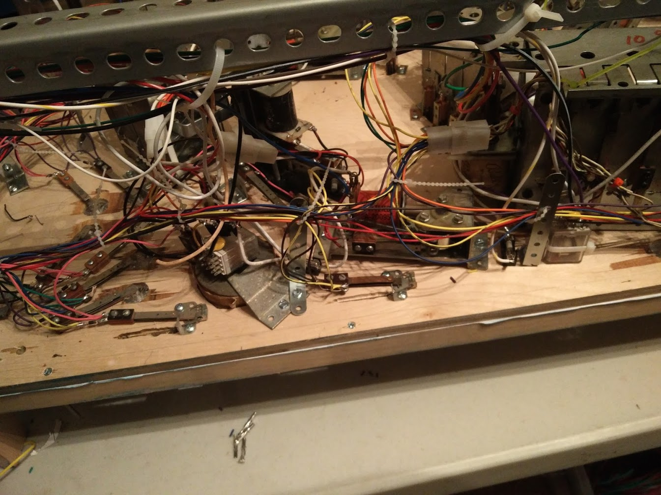
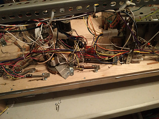
Switch and coil wiring complete!
It's hard to really grasp it from the pictures, but for comparison, here's the relatively empty bottom right corner with a few switches wired from before:

And after:

This area can still use a bit of cleanup, but I ran out of my little metal strips for wiring support as well as the plastic ones.
Also visible here is my attempt to save some more solenoid drivers: two gottlieb pop bumper driver boards. These are wired up to the slingshots. It seems to work fine, and makes me curious why Gottlieb still used EM style driving for their slings while using driver boards for their pop bumpers. Eagle eyed readers will also note that one of those driver boards says NG on it. Surprise surprise, that board was... not good. Instantly locked on one of my slingshots. Genius. I also figured I could very simply enable/disable these by just hooking their logic ground to one of my driver mosfets, but it turns out that makes them glitch and fire randomly when you turn them on and off, so I reverted to doing what gottlieb did, and cutting the ground signal to the switches.
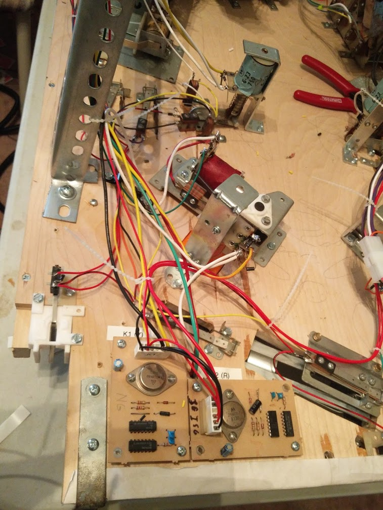
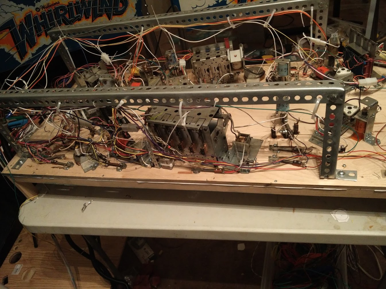
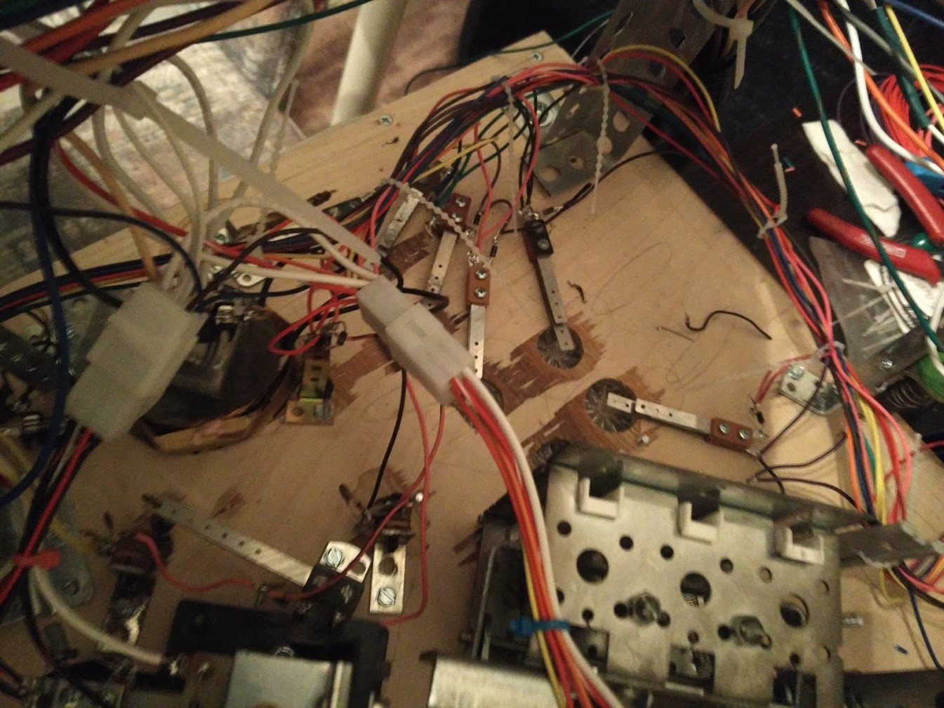
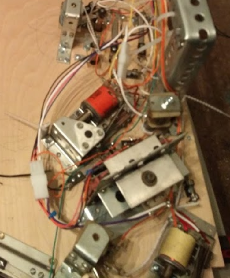
Some more wiring pics:


I was able to mostly follow my sketched wiring from earlier without issue. The one place where it got weird was the mini playfield at the bottom. Since there's no support rail out there, I ended up having to run the solenoid wiring along with the switch wiring around the right flipper to reach it. I'd planned on it going around the lower edge, or between the drops and the flipper mech to leave all the area between and above the flippers open for lights, but there just wasn't room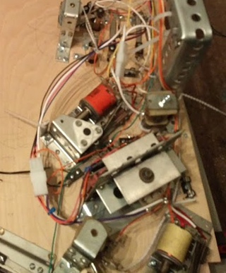
Out of 62 switches, I only had three wiring issues to fix on my first switch test pass, which is nice. Very glad I didn't mess up a whole column or anything. There doesn't seem to be any sure fire way to confirm that a matrix doesn't have any issues, but I knocked down lots of drops and hit lots of switches, and didn't get any incorrect readings.
With that out of the way, I was able to get to the most important part: getting something on the playfield to react!

Now I can start actually coding a few simple rules, and try to play some test games where I imagine different targets are lit and shoot at them to try to get an idea for how my rules to work, and I won't have to stop every 30 seconds to manually reset a bank of targets or eject the ball from a hole
Cross posted from the original Pinside thread, this is one of many posts regarding my third homebrew pinball machine, creatively nicknamed 'P3'
In the midst of wiring, I've been taking some breaks to start on the code. Against my better judgement, I'm going to attempt to write all the game code in Typescript (a type safe superset of javascript), and run it via Node off the Raspberry Pi. I'm a bit worried about performance, but I figure I can always optimize it, shirk off some duties (such as video or sound) to a C backend, or upgrade to a Pi 4 or a x86 based board with a Pi compatible GPIO header at worst. Why Typescript? Because I've been using it at work for so long that trying to use most other languages is unbearable. Typescript is just so nice and developer friendly...
Hopefully this all makes vague sense to people who haven't coded a pinball machine before:
I also am going to try to take a different route from how (to my knowledge) all other pinball games are coded. I've worked with/explored a lot of systems (early williams/bally/gottlieb, wpc, MPF, skeleton game, etc) and they're all very much focused around a central concept: events come in (from switches, timers, etc), and then the code listens to those events, and sets some state (light on/off), fires some coils, etc. It seems to often lead to bugs where lamps get stuck on, balls get stuck in holes, etc, because there's state where there shouldn't be, or there isn't state where there should be.
For instance, on Demolition Man, when you collect the third claw award, it lights the 'car chase' inserts on both ramps. When you finish the mode, it turns them off again. But there's a bug where sometimes, if you drain while in car chase, on your next game, those lights will still be lit! Clearly, it's storing the 'state' of the lamp globally, and then forgetting to turn the state back to 'off' in some edge case. In my mind, that implies something wrong with the methodology they're structuring their code around. The lamp's state should be directly tied to being in car chase mode, it shouldn't be possible to 'forget' to turn if off. I'm sure there were tons more bugs like this that were found and fixed during development we never saw, if this one was able to get through multiple software revisions. I've even seen similar bugs on modern games, like Alice Cooper. On an older game like DM where they were writing in assembly and bytecode, and modes were a new concept, it's understandable that their handling of all this wasn't the cleanest, but with modern games where there can be tons of stacking going on, I want to come up with a cleaner solution for the lights.
Another example of the reverse case is something I've run into on my Taxi. In certain edge cases, the ball will go into one of the eject holes, and then won't kick back out. The game knows the ball is in there, since it registers in switch test, and it doesn't trigger ball search. Somewhere in the complex code surrounding the kickouts, there must be an edge case where it forgets to fire the eject coil. But again, that shouldn't be possible! We have a piece of set continuous 'state' here, which is that the ball is in the hole (the switch is closed), but its tied to a momentary input and output (the switch closing, and the solenoid firing). Since one of those momentary events was missed, the continuous state is now stuck.
In my mind, whenever possible, you want to match up these types of events/states. If a the eject switch is closed, the ball needs to be ejected. That's a 1 to 1 issue. The fact that sometimes, this might result in multiple momentary firings of the eject coil should be abstracted away. Similarly, imagine you had a shot where there's a down post and an opto. The game knows the ball is behind the post, since the opto is blocked, therefore it needs to release it. The same exact situation from a logical perspective: ball in hole/etc, ball needs to be released. But this time it's a down post, which isn't a momentary coil. You just need to energize the post until the ball leaves, no need to repeatedly fire the eject coil like in the first case. So I want to have a system where, in both cases, the game/mode's code is exactly the same. All it would say is something like "coil on if switch closed". Then a separate layer, which actually interacts with the hardware, can take care of things like, is this coil momentary? If so, fire it, then wait a bit. If the game is still requesting the coil to be on, fire it again. Increase the strength if necessary, or maybe trigger an operator alert if too many attempts have failed, etc.
With this in mind, my code works like this:
I have three layers: the game code, the machine driver code, and the actual hardware code. The game code is going to support stacking modes, sub-'modes', etc with their own priorities to override each other, etc. The machine driver code handles turning the 'wants' of the game code into commands for the hardware. In the simple cases this is just stuff like sending the 'turn on coil', 'turn off coil' commands to the hardware, but in cases of more complicated devices, it'll also manage that. For instance, my ramp has a switch to tell when it's up, and I put a switch underneath, to tell if a ball has gotten stuck under the ramp by rolling in from behind while it was down. The 'driver' will handle raising the ramp temporarily if it detects a stuck ball, or giving the lift coil another pulse if it detects the ramp has fallen down when it's supposed to be up. The hardware code will be very simple. It'll just handle reading the switch matrix, toggling IOs, etc, based on what the driver tells it to do.
The driver layer is going to have a list of every 'output' (coils, lamps, etc) the game has. Each mode will be able to specify its own values for any lamp or coil it wants to control. I'm then going to have a system that watches all the modes for when one of those values changes. It'll figure out which modes have priority, etc, and propagate the final value down to the driver. This way, I can have one mode say 'eject the ball from this scoop', but then, if needed, a sub mode that's playing an animation could say 'don't eject the ball right now', and block the coil from activating. When that sub-mode ends, the system will take care of automatically reverting all the outputs' values to remove any effects the sub-mode was having. In the case of lights, I'll also add support for combining values instead of overriding, so for instance I could have one mode say an arrow is green, and another say the arrow is white, but since they're stacked together at the same priority, the driver will take care of flashing the arrow green-white-green-white for them.
Hopefully this is all a good idea....
Cross posted from the original Pinside thread, this is one of many posts regarding my third homebrew pinball machine, creatively nicknamed 'P3'
My ribbon cable connector idea has solidified into a small custom PCB. I would have liked to have this custom fabricated, but the turnaround time is long, and the board is simple. If I'd known exactly what I needed sooner, I would have ordered it with some other boards a few months ago, but oh well.

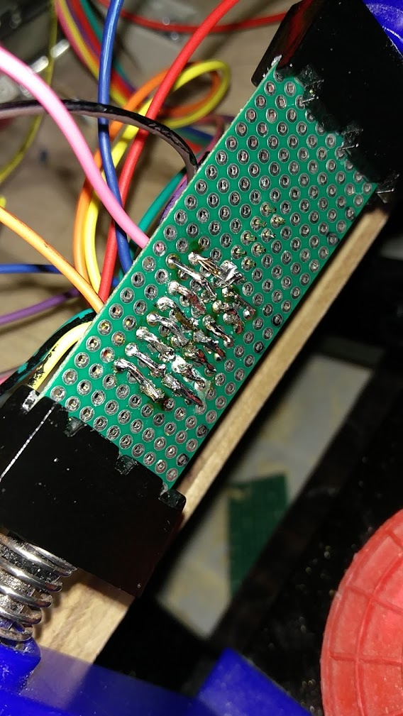
My MPU board has a slot for a 26 pin ribbon cable. 16 columns + 8 rows = 24, but 26 was cheaper. I just ran every wire from the playfield to this board, and soldered them to the pins:
Wouldn't have been too bad, except that, since I want to avoid having any left over wire hanging around, I need to be soldering it while it's within an inch or two of the playfield, sideways ![]() A lot of careful soldering, but luckily no issues
A lot of careful soldering, but luckily no issues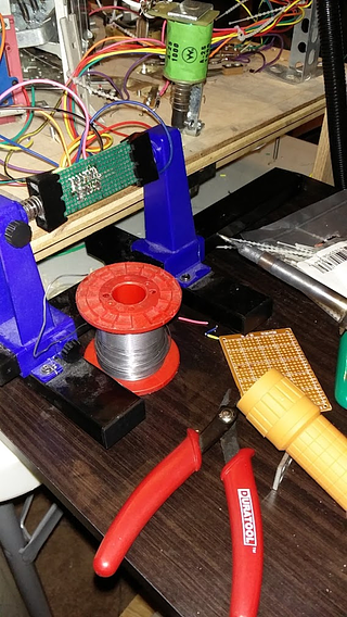
On a custom board I would have made all the wires come in one side, but with no room to route traces here, it still gets a bit messy. 3D printed some simple brackets and mounted it to the very back of the playfield, and it was good to go
Cross posted from the original Pinside thread, this is one of many posts regarding my third homebrew pinball machine, creatively nicknamed 'P3'
Wiring is progressing, not a lot to show...
I'm ending up running two main bundles of wire, one along each outside edge of the playfield, for simplicity. It gets a bit hairy in a few places where mechs are near the edge of the playfield; I need to make sure the wires don't get caught on the cabinet's supports. I guess this is another reason to use a wpc or stern style mounting system... Maybe if I get to a point where I can say the construction is 'done' and I don't need to take the playfield out completely anymore, I'll try to convert. Assuming it fits my playfield...
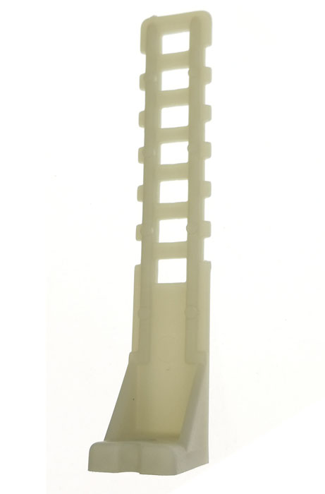
Trying to keep the switch wiring high enough to clear the mechs, and any future lights that get installed, while also keeping it as far from the coil wiring on the support rails. These stern wiring supports are great, and cheap at PBL, but sadly I only have two on hand. Wasn't planning on getting this far when I did my last parts orders, or if these would be useful, and now we're in quarantine so I'm trying to avoid unneeded orders.
To work around that, I found some random strips of metal I had on hand, and bent them. Seems to work just as well, and probably cheaper too, but I'd probably still use the plastic if I had a choice, just to avoid having random metal things to possibly short stuff against.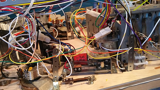
This all looks a bit messy right now, but hopefully once I have all the wires in, and zip tied together into a harness, a lot of the slack will disappear and it'll look cleaner. I also have a lot of coil wiring (like that white loop) where I've had to repeatedly rewire stuff as coils get added or changed, resulting in extra too-long lengths and wire nuts that can be cleaned up eventually. The wiring is going pretty well, and is pretty easy as long as I can reach stuff. The biggest pain is doing the connectors for all the drop target mechs. part of me almost wishes I hadn't bothered with them, but I know I'd regret it down the line. They require a lot of extra planning since you need to have both wires ready ahead of time before crimping, and you need to make sure never to have three wires join at a connector, even though that'd be fine at a regular switch.
I'm also realizing another issue: since I salvaged most of my switches from a Gottlieb playfield, they don't have the third lug for the diode. Right now I'm just sticking a diode on one lug, with the other end hanging free, which hopefully doesn't come back to bite me down the road...
One other hurdle to figure out soon is how to actually hook all these wires to the MPU. Right now I'm just terminating everything in the upper left corner of the playfield, which is vaguely where I picture the switch wiring leaving the playfield, since all the coil wiring is on the right side. I'm hoping I can use a big ribbon cable to connect the playfield to the MPU, to avoid having to assemble more connectors and run a lot of extra wire, since my wire supplies are already running low.
Cross posted from the original Pinside thread, this is one of many posts regarding my third homebrew pinball machine, creatively nicknamed 'P3'
![]() Quoted from atum:
Quoted from atum:
Great idea on the rig! What all colors can you do and mark? Are you limited to black stripe? Or can you put a green stripe on red, etc. to get more possible color combinations with fewer solid (base) wire colors?
I bought all the colors at my local staples: black, white, gold, red, and purple. Weird arrangement, but ok. I used black stripes for the rows, since it was a color I was sure could show up on every wire color I was using. For the columns, since there was so much wire, I just left them blank (the sixth stripe color, invisible). Depending on how I handle lights when I get to that point, maybe they'll use some of the other colors.
I've also been using it to mark some of the coil wires. I managed to get 10 feet x 10 colors of striped 18awg fire off ebay that I used first where possible, but 10 colors is much less than my current 27 coils, and it turns out that 10 feet isn't long enough to reach from the bottom of the playfield all the way to the boards, so I had to reserve the striped wire for only coils on the back third of the playfield. My coil drivers are arranged into 4x 8 pin connectors, so I made one of those with no stripe, one with gold stripe, etc and tried to always use the same color ordering for pins. My rows go red-orange-yellow...purple-pink-brown, and so do my coil connectors, minus the random pre-striped wire thrown in. I've got a giant spreadsheet of all my connector wiring, and also use upper case vs lower case to denote 18 vs 22awg wire, which will allow me to reuse my limited stripe options more.
Coils: 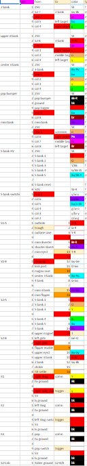
Switches:
![]()
Cross posted from the original Pinside thread, this is one of many posts regarding my third homebrew pinball machine, creatively nicknamed 'P3'
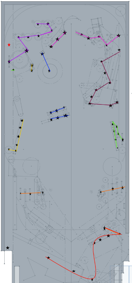
I populated the switch matrix components on the MPU board, and they seemed to test okay with any single switch. Still a bit worried about if the way I'm driving the switch matrix will work once I've got lots of switches down, but so far so good. Luckily, the actual wiring of a switch matrix doesn't really change regardless of how you connect to it, so even if my board ends up being bad, that won't mean rewiring the playfield. With that in mind, I started trying to plan out the matrix, which was surprisingly involved. Technically any switch could go in any position, so all that really mattered was what made wiring easier. I'd already wired up all the target banks as individual rows, so that constrained me somewhat, but beyond that I just tried to lay out all the other rows based on what groups of switches were closest together:
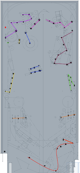
Doesn't look too bad so far!
Then I tried to connect up the columns...
That looks a bit worse. Then I realized I was going about this a bit wrong. No matter what, I was basically going to end up with two big bundles of wire going up each side of the playfield, and then joining at the back. So I need to re-order the rows in a way that will minimize how many rows/columns need to be run to the back, since that's where the most wire will be used. I also don't need the rows/columns to all connect together, since they'll join at the connector anyway, so I can simplify that a bit.
That left me with a new, more concrete wiring plan for the rows: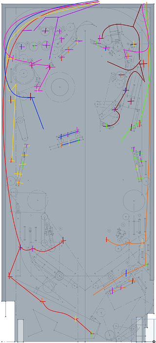
The columns, again, look a lot messier...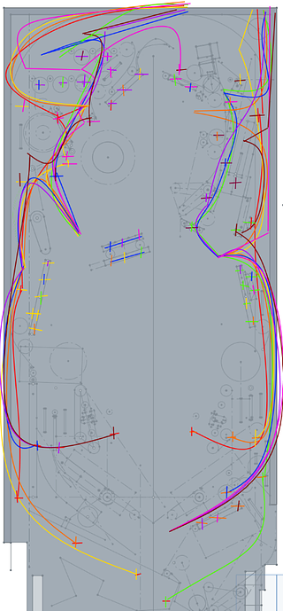
I feel like there must be a way to simplify this more, but I can't see any obvious major changes, and it doesn't look too bad overall. I'd love to see inside the mind of someone who designs the wiring harnesses for these games professionally.
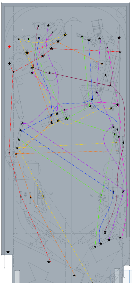
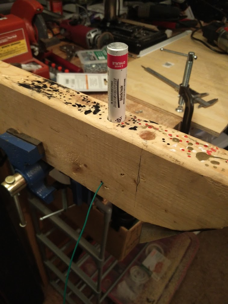
I have nine colors of 22awg wire to work with, and the playfield itself uses 62 switches, which requires an 8x8 matrix. To keep things clean, I'd like to stripe the wires, so I can tell the rows and columns apart when working. Sadly I couldn't find any cheap sources of stranded wire online, so I came up with this:

Tried it first with a regular sharpie, but the ink would rub off quickly, so I got some oil based ones, which seem to stay on the wire well once they dry. Stick a marker in the top, pull your wire through the side, and you'll get a messy but usable stripe.
With that figured out, I started trying to assemble a minimal corner of the switch matrix for more testing, which ended up being the first three columns on one side of thee playfield, and two rows:
Switch matrix still checked out fine, so I'm going to go ahead and wire the rest of the switch matrix
Cross posted from the original Pinside thread, this is one of many posts regarding my third homebrew pinball machine, creatively nicknamed 'P3'
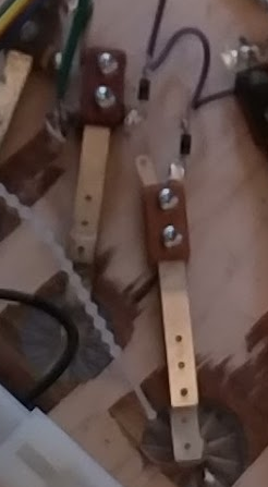
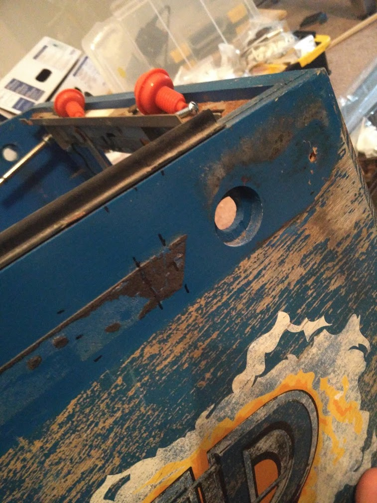
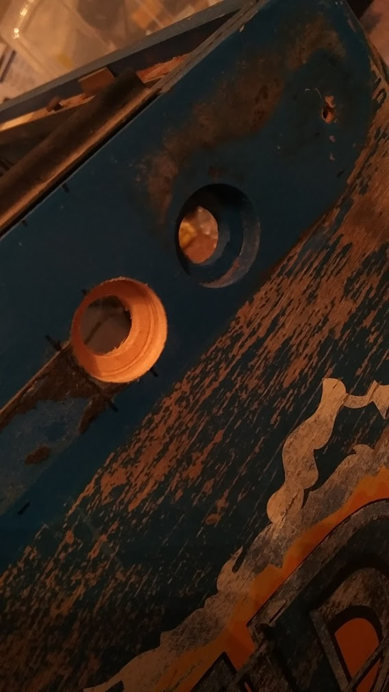
To control the magna save and the outlane saver, I needed my secondary flipper buttons. I took measurements of my Black Knight, WCS, and JM to find out what the spacing should be, and was surprised to find that they were all different! JM's secondary buttons are further back than BK's, while WCS is not only further back, but also isn't 'parallel' to the rail (it looks to be parallel to the bottom of the cabinet instead, which makes it way harder to hit 'in the moment'). Both JM and BK feel okay to me, so I copied BK's spacing.
Luckily, the depression for a williams flipper button seems to be the same diameter as a star rollover, so I was able to use my forstner bit here too. 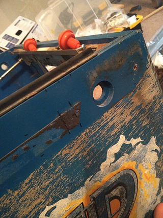
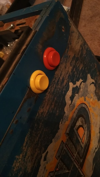
After I installed these, I realized that, in order to use them, I sorta need a switch matrix! That will be my next step