Homebrew Pinball #3, Part 30

Cross posted from the original Pinside thread, this is one of many posts regarding my third homebrew pinball machine, creatively nicknamed 'P3'


Coded the basic structure of the skillshot. I'm pretty dissatisfied with most skillshots in games currently. Most seem to either be 'just plunge the lit lane', or plunge to a flipper and hit a lit shot. You don't really care about your plunge at all. Some games like Deadpool make it a bit more interesting by locking in your lane choice. Most games that actually require you to plunge to a specific spot (such as Taxi) just make you learn one or two plunger positions, which I think can get boring once you've learned them, since at that point you're just slowing down your game to squint at the plunger. My goal here is to have a lot of different places to plunge to, and have the context of the game make you change which one you're plunging to frequently.

There are seven different places to plunge to:

Red: plunge just far enough to clear the diverter. Diverter will close, leading ball to right inlane
Orange: plunge so that the ball hits the lower magnet switch, without hitting upper magnet switch. Magnet activates, pulling ball to the left and feeding upper right flipper (well, hopefully, if I ever get it working)
Yellow: if you plunge past the magnet and hit the upper magnet switch, you'll fall back down and feed the right inlane, similar to the red skillshot
Green: The lower 3 lanes. Not sure what will happen with each lane yet, maybe one will be lit as an extra target
Blue: Upper 3 lanes, same as green
Pink: plunge and fall into the upper eject which will then feed the upper left flipper. Really hard to do, worth the most
Purple: Hard plunge all the way around and feed the left inlane

The Pink and Purple skillshots are made harder since there's a one way gate to the left of the lanes, blocking them. Currently I have it timed so it's open for 2 seconds, then closed for 2, so you'll get redirected to the lanes or let through based on your timing.

Your current 'bet' amount is determined by where you plunge, so you can choose to bet a little or a lot while still keeping it 'pinball'. I'm thinking the bet amounts will be percentages of your total 'bank', so you'll be forced to bet more later in the game. You can return to the shooter lane at any point while playing your poker hand by shooting under the upper right flipper, so you can adjust your bet if your hand is looking better or worse.

In addition, there will be an award on each skillshot, that you can only get if you 'call' your shot by selecting that award with the flipper buttons. Currently it's just points, but I want to eventually put other stuff in there to mix stuff up. If it's only ever points, they'll either just be ignored, or they'll be so big they're unbalanced, so I like to put 'in game' effects into stuff wherever possible. But that will have to wait until I have more game coded to affect.

The graphics themselves on the screen are pretty basic right now, but serviceable. I kinda dread getting to the point where I actually need to make this stuff look nice somehow. Even for a simple screen like this, I think more code is dedicated to drawing and updating the screen than there is to the actual skillshot logic... It must have been nice in the DMD or alphanumeric games where you could often just slap some text up and be done with it

Posted Thursday, October 01, 2020
at 09:43 AM


Tags: Blog Post, Pinball, Project, P3,

Homebrew Pinball #3, Part 29

Cross posted from the original Pinside thread, this is one of many posts regarding my third homebrew pinball machine, creatively nicknamed 'P3'


I've spent a good amount of time playing with the upper magnet. It's positioned next to the shooter lane, right orbit, so that it can drop the ball to the upper right flipper.

The magnet had two use cases:
1. for the skillshot, if you plunge the ball up so that it stops next to the magnet, and then the magnet activates, pulling the ball sideways from the shooter lane to then release it to the flipper
2. to feed the upper flipper via left orbit shots. this is the main use case, with the skillshot just being a bonus. I didn't really forsee a problem with this while designing, but I've come to realize that this just isn't how magnets are normally used in machines. Games like Twilight Zone will stop a fast moving ball on an orbit, but they have the magnet directly under the ball's path. The magnet acts only as a ball grabber, not a diverter. Most cases I can find of magnets being used as diverters are things like TWD's crossbow, or WCS's lock. WCS is the closest to my use case, since it specifically grabs a moving ball, stops it, then drops it. But even WCS has issues grabbing a fast moving ball.

I quickly discovered that my original plan of wiring and mounting this magnet the same way the magna save is mounted just won't work. The magna save coil is being powered using 25V, while most newer games use 50V for their magnet. So I hooked up my 50V line to my magnet relay, instead of 25V, and... immediately fried my relay. The 50V is strong enough that, when the relay deactivates and its contacts move apart, the voltage will just arc across the gap and continue powering the magnet while melting the contacts. I had a similar issue with the 5-bank reset coil, and was able to fix it by adding a 10uF, 300V capacitor across the contacts. For some reason this doesn't work on the magnet. I wondered if the magnet was stronger, but the magnet actually has more resistance than the drop target coil. My random relay was only rated for 3A@25V though, so I ordered a really beefy relay, which was rated for 30A (!). I think my magnet should be drawing about 10-12A at 50V, so that should be plenty. But that relay also had constant arcing issues. I tried bigger snubber capacitors, other snubbing solutions, even disassembling the relay and physically bending it so the contacts are farther apart, and nothing helped.

It seems like switching 50V@10A just isn't reliable via a relay somehow, though I don't understand why. Modern games all control their magnets via transistors and mosfets, although I don't know if that is specifically to avoid this issue, or for other reasons. The problem is, I can't use those here, since my 50V has a separate ground from my 25V. My next plan is to get a TIP36C (which is what williams used for their 50V coils in the 90s), and then try to use a relay to switch the gate (instead of having a microcontroller switch it like normal) which feels like horrible overkill, but it may work. Even at that point, I'll still have issues because I can't PWM a relay, so I'll basically be running the magnet at full power. I'm not sure how long I can power the magnet like that, hopefully it's long enough to get the ball settled.

The magna save is also a completely 'below playfield' magnet, with no visible core. Adding a core that goes all the way through the playfield helps make the magnet stronger, and I assume that this is why games like TWD, which need to grab a ball shot at their wide bash toys, use an even bigger exposed magnet core. At first I figured I should just order one of those larger exposed cores, but they're incredibly expensive somehow (the large core costs more than the magnet itself!). Even a regular size core is expensive. I don't really want to spend that much money on something that may not even be useful, so for now I've just bought some 3/4" steel roundstock that I'll use to test the smaller exposed core. I can't find any info on how much stronger this make the magnet.

All this is still up in the air, too, as I don't know if the magnet will be able to grab the ball properly even with a large core and 50V, given the crazy speed my left orbit shot has. I've spent a lot of time trying just to get the 50V to work, and still haven't been able to even do a single test yet to see if the 50V can grab the ball since it keeps melting stuff

I'm also trying to consider other approaches, such as replacing the magnet with a physical diverter, but currently I can't find any good way to fit one in with my current constraints, and I would still need a magnet or an up post to hold the ball for a reliable side flipper shot after the diverter gets the ball to the flipper...

I may also try putting an up post in the shooter lane, specifically to stop the ball as it comes down the lane from the left orbit, and then using the magnet to pull the stopped ball over the flipper. I am running low on drivers for the coils though, so I want to avoid adding in more coils if possible...

Posted Tuesday, September 29, 2020
at 08:58 PM


Tags: Blog Post, Pinball, Project, P3,

Homebrew Pinball #3, Part 28

Cross posted from the original Pinside thread, this is one of many posts regarding my third homebrew pinball machine, creatively nicknamed 'P3'


Got the basic habitrail installed. Made a half height, low quality mount to hold the other end, which seems to work okay.

It looks like I can make the curve on the entry mount wider for a smoother feed. This is the original:

And here's my current iteration:

Mounting the entry mount was also an issue, since I didn't really plan for that. I ended up putting it on a standoff on top of one of the existing ramp's mounting holes, but I still only have one screw holding it. It seems to work okay, so I'll leave it for now. I could probably extend another support out to the posts behind the 2-bank if necessary, but I don't want to cover the playfield any more than necessary.

I also needed a place to mount the switch, so I stuck a microswitch through a small gap. To prevent airballs, I put holes on the top to screw a sheet of clear plastic into. Still need to figure out how to attach the plastic on the left side of the ramp. I don't understand how Mars never has airball issues on its ramp... seems hard to believe that they managed to make it the exact height needed for their flipper strength, especially since I'm using the same flippers!

This is my final entry design. Looks pretty weird, but it works. :

I had to add some side rails to keep the ball from falling off, especially at higher speeds. Lock post worked on my first try with a random guess for the pulse length, which surprised me.

While it's nice to know this works, I probably will avoid locking multiple balls this way, since I don't have any way to mount a switch behind it to know if it failed to release a ball due to the ramp positioning. Sadly, this was the only position I could fit the post mech in, so I'm a bit constrained here. I'mthinking I'm going to have most multiballs work by locking one ball on the ramp, and then you get a second ball to plunge, and the ramp ball is released once you hit a switch. Maybe there will also be something to let you short plunge and combo up the ramp to lock a second ball, for three ball, or a rule about locking both balls during MB to release a third. Since there's no auto plunger I can't really have a normal add a ball. I feel like multiballs lately have been a bit boring design wise, so I'm hoping to do more stuff with multiple phases like DE used to do, or maybe more advanced stuff like a special multiball that you can only work towards qualifying while you're already in another multiball, at the cost of ignoring the current multiball's jackpots to make that progress...

For normal ramp shots, I programmed the game to engage the post as soon as the ball makes the ramp, and then disengage once the inlane switch registers, but I had issues with the ball bouncing over the switch since it was just dropping off the end.Inspired by Metroid which I saw at Pintastic last year, I made this end cap for the rail to make the ball drop nicely.

It worked, but I didn't like how it looked, so I made this instead, which seems to work fine and looks more natural:

Posted Tuesday, September 29, 2020
at 06:30 PM


Tags: Blog Post, Pinball, Project, P3,

Homebrew Pinball #3, Part 27

Cross posted from the original Pinside thread, this is one of many posts regarding my third homebrew pinball machine, creatively nicknamed 'P3'


Here's a big case of 'wish I was using MPF'... Testing live on the machine was a pain since it was at the other end of the house from my regular computer. So I wanted to be able to easily test stuff virtually. MPF has a nice application for this. Lets you import a picture of your playfield, then drag and drop switches, lights onto it. Pretty handy, so I recreated it using my new rendering capabilities. Not a ton of work in the end, although mine lacks some polish...

Squares are switches. Red means closed, yellow/white means open. Left click to toggle open/shut, right click to quickly press the switch and release it again. Diamonds are coils, they turn red when energized. The white circle above the right inlane is a light, currently off, currently wired up as a 'lower ramp w/lit'.
Another in the left outlane will turn green when the mini-playfield is enabled, triggering the down post to let the ball in. Hopefully I can use this to get a slightly better feel for where lights will go.

I also added some code to do stuff like automatically opening the drop target switches when the bank resets, auto closing the shooter lane switch after a ball is released from the trough, etc. Stuff that would happen physically on a real machine. Otherwise it gets to be a pain to use, since the drop target coils would repeatedly fire until you remembered to click each switch again

Posted Tuesday, September 29, 2020
at 06:30 PM


Tags: Blog Post, Pinball, Project, P3,

Homebrew Pinball #3, Part 26

Cross posted from the original Pinside thread, this is one of many posts regarding my third homebrew pinball machine, creatively nicknamed 'P3'


Code can't get very far without some read-outs. I don't have any lights yet, so for now my 'screen' will have to do. Currently that 'screen' is a 50' HDMI cable running to my livingroom TV, but it'll do.... I spent a long time trying to find a good R-Pi compatible graphics library that would work with Typescript/Node. For some reason, everything seems to have been abandoned 2-3 years ago, and doesn't work with modern Pi operating systems. I'd be fine with even coding the graphics from scratch with a plain OpenGL context, but even a simple library to provide that seemed to be missing.

Eventually, I found a simple library that supported things like basic shapes, images, and text, that was designed specifically for RPi game dev, but had been abandoned partway through development. The author's last update said that they were working on keyboard/mouse support, since without that a game graphics library isn't very useful. Well, it's useful to me! no keyboards here...

Only problem was, it didn't work with the latest RPi OS, since they introduced a new graphics card driver, and it wasn't compatible with Windows (my dev OS). So I dug in, forked it, and made my own version with RPi 3 support, some features and bug fixes, and, with one late night hacking session, a shaky but usable windows port. Not too bad, all things considered. The nice thing about this, vs using an established library (if one had existed), is that if I find any other bugs or shortcomings, I can just easily add whatever I need, since I'm already maintaining my own fork.

With that out of the way, I got some initial status displays set up. Very rough currently; I am not in any way an artist. Hopefully I can work up something half decent for the screen at least, but actually doing some art for the playfield is probably beyond me... More mountains to climb down the road

I can add more cards from the drop targets

No scoring or ball logic hooked up yet though... I also need to figure out what exactly is actually going to happen once you complete a hand. To keep with the 'real poker' goal, technically you should have a final opportunity to bet before your opponent reveals their cards, so I figure you'll need to shoot a shot that can hold the ball to finally flip the cards and declare a winner. In this case, my only ball holds are the upper eject hole, the ramp, and the shooter lane, so I'll have to figure out some logic for that, as well as how exactly you can 'fold' if your hand is looking bad. I'd like it to be something on the playfield, vs some menu interaction, but it has to be something very hard to hit accidentally....

Current lines of code: 4,106

Posted Friday, September 25, 2020
at 10:25 AM


Tags: Blog Post, Pinball, Project, P3,

Homebrew Pinball #3, Part 25

Cross posted from the original Pinside thread, this is one of many posts regarding my third homebrew pinball machine, creatively nicknamed 'P3'


Began work on the habitrail for the ramp, to return the ball to the left inlane. I 3D printed some clips with flat bottoms to make it easy to hold the rails while I align them and work. The plan is eventually to either use some brass and solder it, or try to braze some steel, but for now, I'm using some easy to bend 1/8" copper wire (and cheap, since it's just on spools at Home Depot) to get it right and test things. I'm curious to see if the clips can hold up to soldering/welding, it'd be convenient.

The actual alignment is a bit iffy; since my ramp model didn't match the actual model that means the habitrail I drew won't line up with the physical ramp either. I tried to eye-ball adjust it to match where it looks like the ramp actually is, but we'll see how well that works.

The actual attachment to the ramp will also be weird. It was designed to connect to a plastic tube that goes across the playfield, and didn't have much flow. Originally I just sorta hand-waved this part as "I'll make something to hold the habitrail, can't be that bad", but now I'm at the part where I need to actually figure out how to connect a ramp whose shape I don't know to the habitrail I haven't built yet.... Here's my first attempt. I'll probably just have to print this a lot of times to get the fit right, assuming the basic shape even works.

Posted Thursday, September 24, 2020
at 10:36 PM


Tags: Blog Post, Pinball, Project, P3,

Homebrew Pinball #3, Part 24

Cross posted from the original Pinside thread, this is one of many posts regarding my third homebrew pinball machine, creatively nicknamed 'P3'


Earlier, I went searching for an LCD to put in the middle of the playfield. After a lot of digging, I ordered this 9" screen from AliExpress. Seems to have HDMI support and can be powered with my ATX power supply, but it's hard to tell for sure. There's a ton of different badly documented screens for sale, with conflicting information about what they support or how to drive them. It seems like there's really only two driver boards floating around, one with VGA support and one without, judging by the pictures, but some of the items for sale are clearly wrong about what they're offering. Lots of fun. But for ~$30, I'll take some gambles. Any screens for sale from more reputable US sources seem to be $100+ which is a bit ridiculous. Originally I planned to just buy a monitor and strip off the case, but it's hard to even find a 9" monitor, and the more common 10" won't fit my playfield.

Sadly it's been more than a month since I ordered the screen, and it still hasn't arrived. Tracking last showed it leaving China on 3/30, so not sure if it's gotten lost or just stuck in customs or something forever...

Not a super big deal, I guess, since I don't have any way to really mount it yet.

I'm investigating different options for plastic to cover the hole. Not sure what material is best as far as being pretty sturdy but also thin and scratch resistant. Based on the Voyager homebrew, I'm also wondering about just using a single large sheet of plastic for the playfield as opposed to recessing a smaller cover. I wouldn't have to worry about routing out the recess for the window, or about doing any inserts either, and no need to clearcoat. A lot of other possible issues arise though, so that'll need some more investigation. Once I can find better what material to use, I'll try to order some sheets for experimenting

Posted Thursday, September 24, 2020
at 10:35 PM


Tags: Blog Post, Pinball, Project, P3,

Homebrew Pinball #3, Part 23

Cross posted from the original Pinside thread, this is one of many posts regarding my third homebrew pinball machine, creatively nicknamed 'P3'


While getting some basic code running to reset the drop targets and eject the holes, I suddenly lost an entire bank of solenoids. Inspecting the board, I eventually figured out that the board had been repaired so many times as I modded it to test different things that one of the traces carrying the solenoid ground had just gotten ripped off completely. At this point it probably had 4 jumpers on it already, and multiple cut traces, plus some of the mosfets had been replaced three times, so I decided it was time to junk that pcb and build a new one.

One of the main issues that required all those modifications early on was my changing requirements for how the inputs would work. First I'd had them active high, then active low, and then I'd had to change which pin they were. Back when that happened, I redesigned the board to add some more configuration points, so each I/O could have a configurable pull up/down, as well as fix some other pain points. I added LED indicators that the fuses were good, test points for the voltages, and combined my 6/6/4 pin connectors into two 8 pin connectors. A big goal on these boards as I design them further is just making the connector count as small as possible, since they needed to get unplugged so often. I'd actually had the new PCBs on hand for months, but hadn't needed to actually use one yet, so I started assembling:

Sadly, I discovered an issue with my design early on: at some point I had mirrored some of the components. For the mosfets, that wasn't too bad; just turn them around, but I'd also mirrored one of my 16 pin chips, which resulted in the horrible hack of mounting the chip upside down:
Sigh. I guess another pass at the design will be needed down the line. It'll work for now though, just hard to mount

Posted Thursday, September 24, 2020
at 12:24 PM


Tags: Blog Post, Pinball, Project, P3,

Homebrew Pinball #3, Part 22

Cross posted from the original Pinside thread, this is one of many posts regarding my third homebrew pinball machine, creatively nicknamed 'P3'


Switch and coil wiring complete!

It's hard to really grasp it from the pictures, but for comparison, here's the relatively empty bottom right corner with a few switches wired from before:

And after:

This area can still use a bit of cleanup, but I ran out of my little metal strips for wiring support as well as the plastic ones.

Also visible here is my attempt to save some more solenoid drivers: two gottlieb pop bumper driver boards. These are wired up to the slingshots. It seems to work fine, and makes me curious why Gottlieb still used EM style driving for their slings while using driver boards for their pop bumpers. Eagle eyed readers will also note that one of those driver boards says NG on it. Surprise surprise, that board was... not good. Instantly locked on one of my slingshots. Genius. I also figured I could very simply enable/disable these by just hooking their logic ground to one of my driver mosfets, but it turns out that makes them glitch and fire randomly when you turn them on and off, so I reverted to doing what gottlieb did, and cutting the ground signal to the switches.

Some more wiring pics:

I was able to mostly follow my sketched wiring from earlier without issue. The one place where it got weird was the mini playfield at the bottom. Since there's no support rail out there, I ended up having to run the solenoid wiring along with the switch wiring around the right flipper to reach it. I'd planned on it going around the lower edge, or between the drops and the flipper mech to leave all the area between and above the flippers open for lights, but there just wasn't room

Out of 62 switches, I only had three wiring issues to fix on my first switch test pass, which is nice. Very glad I didn't mess up a whole column or anything. There doesn't seem to be any sure fire way to confirm that a matrix doesn't have any issues, but I knocked down lots of drops and hit lots of switches, and didn't get any incorrect readings.

With that out of the way, I was able to get to the most important part: getting something on the playfield to react!

Now I can start actually coding a few simple rules, and try to play some test games where I imagine different targets are lit and shoot at them to try to get an idea for how my rules to work, and I won't have to stop every 30 seconds to manually reset a bank of targets or eject the ball from a hole

Posted Wednesday, September 23, 2020
at 03:23 PM


Tags: Blog Post, Pinball, Project, P3,

Homebrew Pinball #3, Part 21

Cross posted from the original Pinside thread, this is one of many posts regarding my third homebrew pinball machine, creatively nicknamed 'P3'


In the midst of wiring, I've been taking some breaks to start on the code. Against my better judgement, I'm going to attempt to write all the game code in Typescript (a type safe superset of javascript), and run it via Node off the Raspberry Pi. I'm a bit worried about performance, but I figure I can always optimize it, shirk off some duties (such as video or sound) to a C backend, or upgrade to a Pi 4 or a x86 based board with a Pi compatible GPIO header at worst. Why Typescript? Because I've been using it at work for so long that trying to use most other languages is unbearable. Typescript is just so nice and developer friendly...

Hopefully this all makes vague sense to people who haven't coded a pinball machine before:

I also am going to try to take a different route from how (to my knowledge) all other pinball games are coded. I've worked with/explored a lot of systems (early williams/bally/gottlieb, wpc, MPF, skeleton game, etc) and they're all very much focused around a central concept: events come in (from switches, timers, etc), and then the code listens to those events, and sets some state (light on/off), fires some coils, etc. It seems to often lead to bugs where lamps get stuck on, balls get stuck in holes, etc, because there's state where there shouldn't be, or there isn't state where there should be.

For instance, on Demolition Man, when you collect the third claw award, it lights the 'car chase' inserts on both ramps. When you finish the mode, it turns them off again. But there's a bug where sometimes, if you drain while in car chase, on your next game, those lights will still be lit! Clearly, it's storing the 'state' of the lamp globally, and then forgetting to turn the state back to 'off' in some edge case. In my mind, that implies something wrong with the methodology they're structuring their code around. The lamp's state should be directly tied to being in car chase mode, it shouldn't be possible to 'forget' to turn if off. I'm sure there were tons more bugs like this that were found and fixed during development we never saw, if this one was able to get through multiple software revisions. I've even seen similar bugs on modern games, like Alice Cooper. On an older game like DM where they were writing in assembly and bytecode, and modes were a new concept, it's understandable that their handling of all this wasn't the cleanest, but with modern games where there can be tons of stacking going on, I want to come up with a cleaner solution for the lights.

Another example of the reverse case is something I've run into on my Taxi. In certain edge cases, the ball will go into one of the eject holes, and then won't kick back out. The game knows the ball is in there, since it registers in switch test, and it doesn't trigger ball search. Somewhere in the complex code surrounding the kickouts, there must be an edge case where it forgets to fire the eject coil. But again, that shouldn't be possible! We have a piece of set continuous 'state' here, which is that the ball is in the hole (the switch is closed), but its tied to a momentary input and output (the switch closing, and the solenoid firing). Since one of those momentary events was missed, the continuous state is now stuck.

In my mind, whenever possible, you want to match up these types of events/states. If a the eject switch is closed, the ball needs to be ejected. That's a 1 to 1 issue. The fact that sometimes, this might result in multiple momentary firings of the eject coil should be abstracted away. Similarly, imagine you had a shot where there's a down post and an opto. The game knows the ball is behind the post, since the opto is blocked, therefore it needs to release it. The same exact situation from a logical perspective: ball in hole/etc, ball needs to be released. But this time it's a down post, which isn't a momentary coil. You just need to energize the post until the ball leaves, no need to repeatedly fire the eject coil like in the first case. So I want to have a system where, in both cases, the game/mode's code is exactly the same. All it would say is something like "coil on if switch closed". Then a separate layer, which actually interacts with the hardware, can take care of things like, is this coil momentary? If so, fire it, then wait a bit. If the game is still requesting the coil to be on, fire it again. Increase the strength if necessary, or maybe trigger an operator alert if too many attempts have failed, etc.

With this in mind, my code works like this:
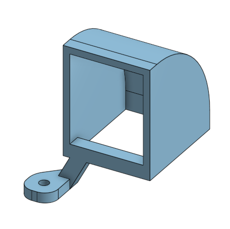
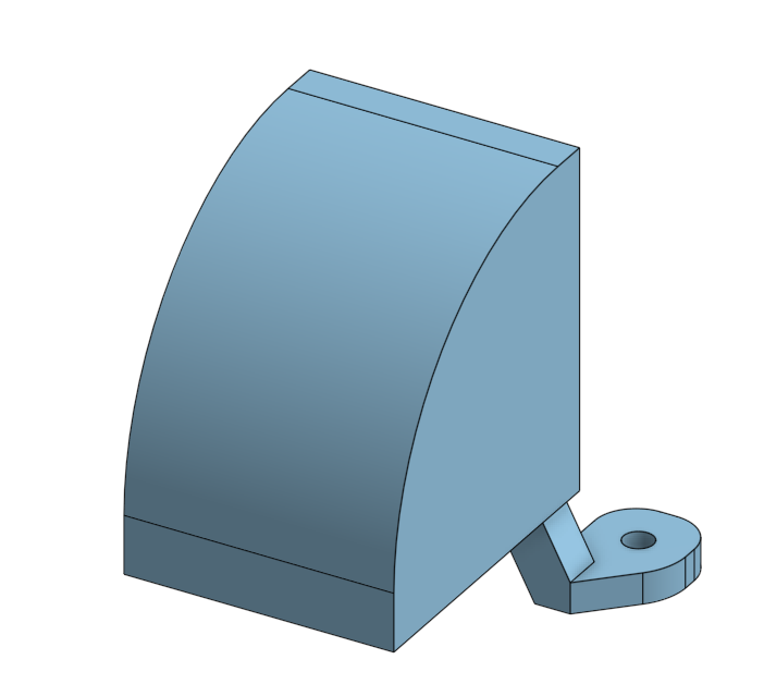
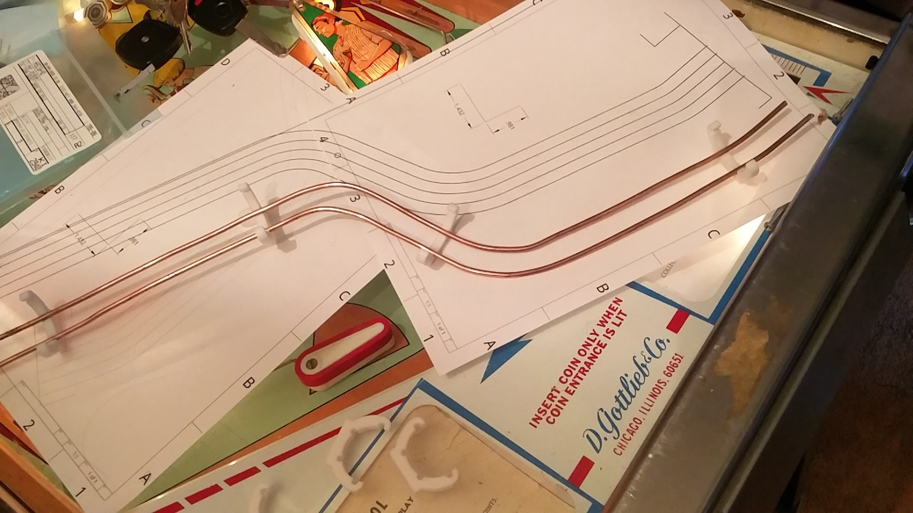
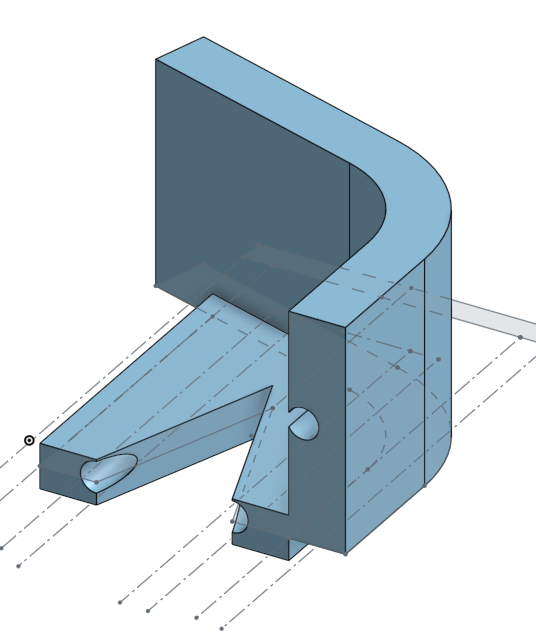
I have three layers: the game code, the machine driver code, and the actual hardware code. The game code is going to support stacking modes, sub-'modes', etc with their own priorities to override each other, etc. The machine driver code handles turning the 'wants' of the game code into commands for the hardware. In the simple cases this is just stuff like sending the 'turn on coil', 'turn off coil' commands to the hardware, but in cases of more complicated devices, it'll also manage that. For instance, my ramp has a switch to tell when it's up, and I put a switch underneath, to tell if a ball has gotten stuck under the ramp by rolling in from behind while it was down. The 'driver' will handle raising the ramp temporarily if it detects a stuck ball, or giving the lift coil another pulse if it detects the ramp has fallen down when it's supposed to be up. The hardware code will be very simple. It'll just handle reading the switch matrix, toggling IOs, etc, based on what the driver tells it to do.

The driver layer is going to have a list of every 'output' (coils, lamps, etc) the game has. Each mode will be able to specify its own values for any lamp or coil it wants to control. I'm then going to have a system that watches all the modes for when one of those values changes. It'll figure out which modes have priority, etc, and propagate the final value down to the driver. This way, I can have one mode say 'eject the ball from this scoop', but then, if needed, a sub mode that's playing an animation could say 'don't eject the ball right now', and block the coil from activating. When that sub-mode ends, the system will take care of automatically reverting all the outputs' values to remove any effects the sub-mode was having. In the case of lights, I'll also add support for combining values instead of overriding, so for instance I could have one mode say an arrow is green, and another say the arrow is white, but since they're stacked together at the same priority, the driver will take care of flashing the arrow green-white-green-white for them.

Hopefully this is all a good idea....

Posted Wednesday, September 23, 2020
at 09:39 AM


Tags: Blog Post, Pinball, Project, P3,

< Newer Posts
Older Posts >

Posts per page: 5 10 25 50 100